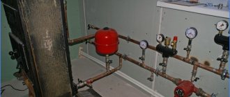
Air vents: the main task
The device for venting air from the heating system makes it possible to remove gases accumulated in the pipeline and radiators.
Airing of the system occurs for a number of reasons, including
:
- Due to the high content of dissolved gases in the coolant, which has not undergone special training - deaeration. The solubility of gases depends on the temperature of the medium, and when the coolant is heated, the air is separated from the water and accumulates, forming plugs.
- Due to the excessively rapid filling of the circuit with the coolant, the liquid in the branched network does not have time to displace the air in a natural way. The coolant must be poured from the bottom point so that air is forced upward and out through the open valve.
- Due to the penetration of air through the walls of the polymer pipeline, if it is made of a material without a special anti-diffusion coating. When choosing pipes, this point should be taken into account.
- In the course of repair work related to the replacement of elements without completely draining the coolant - in this case, the repaired heating device or circuit is cut off from the rest of the system, and then connected back.
- Loss of tightness.
- As a result of corrosive processes - when oxygen interacts with iron, hydrogen is released from the air molecule, which also accumulates in the system.
Why is the air in the heating system dangerous?
The air dissolved in the coolant gradually destroys steel pipes and radiators, elements of the boiler unit. The corrosive activity of air, which was first dissolved in water and then released during heating, significantly exceeds the parameters of atmospheric air due to the increased oxygen content.
Installation locations of air separators in the system
The gases accumulated in the pipeline not only provoke or accelerate the corrosion of metal elements, but also form air locks that prevent the heating system from fully functioning
:
- Due to gas plugs, the circulation of the coolant deteriorates; in serious cases, the movement of liquid through the pipes can be completely blocked. In such a situation, heating devices cool down quickly.
- Air locks work as a heat insulator, and if gases accumulate in the upper part of the battery, it warms up worse and gives less thermal energy to the room.
- In the presence of air locks, the movement of the coolant along the heating circuit is accompanied by loud gurgling sounds and gurgling, which violates the acoustic comfort in the house.
- Circulation pumps are not designed for pumping gases; when working with an air-filled coolant, the bearing and impeller of the pump unit wear out much faster.
Special air venting devices allow solving the problems associated with airing the heating system. It is important to choose the right valves for bleeding air and correctly determine the location of these elements.
Types of air vents
To remove air locks in the central heating system, it is planned to install drain valves on the extreme radiators in each branch. Valve valves make it possible to bleed the air displaced to the extreme point of the branch when the system is filled with a coolant.
Autonomous heating systems, as well as new radiators connected to the central heating network, are equipped with special air vent valves.There are two types of devices - an automatic air release valve and a manual valve (Mayevsky valve).
The devices are selected taking into account the principle of operation and ease of use, they are mounted in those places of the heating circuit where the risk of formation of air locks is greatest - on the upper manifold of each radiator, at the highest point of the heating system.
Automatic air vent
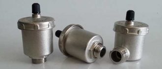
The automatic air valve consists of a hollow cylinder with a plastic float inside. The device is installed vertically, its internal chamber is normally filled with a coolant, which flows under pressure through an opening in the lower part of the chamber. The air vent is equipped with a needle outlet valve - it is to this valve that the float is attached to the lever.
The principle of operation of the automatic air vent
When an air lock forms in the pipeline, it tends to the highest point of the radiator or the heating circuit as a whole. If an air valve operating in automatic mode is installed in this place, the coolant from its inner chamber is displaced by gases. When the liquid is displaced, the float goes down and opens the valve, as a result of which gases are released from the heating pipeline, and the chamber is again filled with coolant.
Note! The valve for automatically venting air from the heating system becomes silted over time, overgrown with scale. This leads to jamming of the mechanism, loss of valve tightness - moisture begins to seep through it. Such a device requires replacement - automatic air vents cannot be repaired.
The amount depends on the characteristics of the heating system.
Device required for installation
:
- as part of the safety group of the boiler unit at the outlet of the water jacket, where the coolant is heated to the maximum temperature;
- at the highest point of vertical risers - it is there that gaseous substances rise and accumulate;
- on distribution manifolds of underfloor heating so that air can be vented from the circuits;
- on U-shaped loops made of polymer pipes, which are equipped to compensate for the thermal expansion of the pipeline.
Manual air vent
The manually operated drain valve is commonly known as the Mayevsky tap. This device has no moving elements, therefore it is more durable and more reliable than automatic.
The cylindrical body of the air vent is provided with an external thread. The longitudinal through hole in the housing is closed by a screw with a cone-end. A circular channel extends from the central hole.
The principle of operation of the Mayevsky crane is extremely simple: unscrewing the screw frees the passage into the side channel, due to which the accumulated gases go out through the hole in the body. After removing the airlock, the screw is tightened into place.
Type of manual angle air vent with shut-off cone
Manual air vent valves are designed for pipe mounting as standard. But the greatest demand is for Mayevsky's radiator taps, which are mounted on sectional and panel-type heating devices.
Air in the engine cooling system: how to remove an airlock
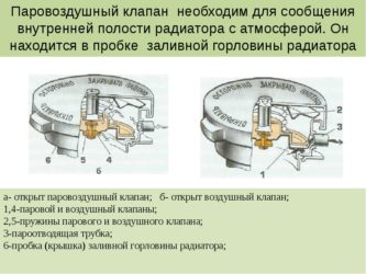
The cooling system of the car engine, although not completely closed, is not provided for the ingress of air into its circuits. The formation of an air lock in the engine cooling system is a problem that leads to malfunctions, which result in engine overheating, insufficient stove performance, etc.
Also, in the case of airing the cooling system, the readings of the temperature sensors on the instrument panel may be incorrect. One way or another, the problem needs to be solved, and in a timely manner.Next, we will talk about how to remove the airlock and how the cooling system is vented.
How to expel an airlock in the engine cooling system
Before moving on to the process of removing air pockets from the cooling system, let's start with the main reasons why they appear.
- First of all, it is worth mentioning the depressurization as a result of the violation of the connections of pipes, hoses and nozzles. All this leads to the fact that the system sucks in air through leaks at the joints. Also, air jams are formed when antifreeze / antifreeze is topped up.
- It is also worth highlighting the irregularities in the operation of the air valve. As you know, when heated, the antifreeze in the system expands, the pressure rises, but when it cools, the valve is responsible for equalizing the pressure. If the pressure is low, the valve lets air in from the outside. If problems arise with this valve, excess air accumulates in the system.
- Sometimes the pump seals stop sealing the system, which leads to air leaks. Also, antifreeze can flow, its volume naturally decreases and excess air accumulates.
So, having dealt with the reasons, let's move on to the consequences and signs that the cooling system is airborne. Immediately, we note that the consequences can be quite serious. An air lock can disrupt the circulation of antifreeze, especially if the air does not allow the coolant to pass into the radiator. As a result, the motor overheats.
Also, the stove starts to work poorly in the cabin, which reduces comfort when using the vehicle in winter and can pose a threat to the health of the driver and passengers. To solve the problem, you need to know how to remove air from the engine cooling system. At the initial stage, you should make sure that the level of antifreeze is normal, as well as the cooling system itself is tight, that is, there are no leaks.
To do this, you need to inspect all rubber parts, hoses, pipes, fittings, etc., and with the engine running. Detecting a leak will require immediate repair. If there are no leaks, but the motor overheats or, conversely, remains cold for a long time, you need to check the thermostat.
It often happens that the device wedges in the open or closed position (the coolant circulates only in a small or large circle). Less commonly, the cause is an air lock in the area of the thermostat.
How to remove an airlock: methods
As mentioned above, the most accurate and common sign of an airlock is cold air from the stove, while the engine is completely warmed up. To get rid of air in the system, there are several available methods (depending on the type of internal combustion engine, implementation features of its cooling system, etc.).
- You can air the cooling system by removing the pipes through which coolant is supplied to heat the throttle. For this, the plastic cover is removed from the motor, after which free access is opened. Having found the pipes, you need to remove one of them.
Then the cover of the expansion tank is unscrewed, then a clean rag is applied to the neck, then you can blow into the tank. When doing this, do not allow coolant to come into contact with the eyes, on exposed skin or inside! Antifreeze and TOSOL are the strongest poison!
The tank should be purged until antifreeze flows from the removed branch pipe. Next, the removed tube must be fixed in place, if necessary, add coolant and tighten the tank cap.
- The next method is somewhat simpler than the previous one and is similar to it. First, warm up the engine and then turn off the engine. In this case, the cover of the expansion tank does not need to be unscrewed.
It is enough just to remove one of the nozzles on the throttle and wait until coolant flows from there. Next, you need to tightly fasten the pipe by tightening it with a clamp. It is important to take into account that the antifreeze / antifreeze flowing out of the nozzle can be very hot, so care must be taken not to get burned and injured.
- The last method of airing the engine cooling system is distinguished by its simplicity and high efficiency. It is necessary to drive the car uphill so that the "nose" is at the top point. Then you need to apply the parking brake, you can put chocks under the rear wheels so that the car does not roll. We also recommend reading the article on how a comprehensive diagnosis of the car engine cooling system is performed. From this article, you will learn about the main stages of checking the specified system and its individual elements.
Next, you need to unscrew the radiator / expansion tank caps. Then the engine is started and allowed to warm up. During warming up, it is necessary to strongly gasify in several approaches, while the coolant level in the tank is monitored and topped up. This procedure must be continued until the air bubbles disappear. Then all plugs can be tightened.
How to remove an airlock
Ideally, gases rise to the highest points in the circuit where air vents are installed and are vented from there by manual or automatic valves. In practice, errors in the design or installation of the pipeline lead to the formation of air jams in hard-to-reach places.
To remove such a plug, it is necessary to find its location - by the murmur of the coolant flowing through the air-filled section, by the relatively low temperature of the pipe or radiator, by the ringing sound when the pipes are tapped.
An increase in the temperature of the coolant and / or pressure in the system will help to expel the plug from the autonomous heating system. To apply pressure, it is necessary to open the make-up valve and the drain valve closest to the air plug (in the direction of flow). The water entering the system increases the pressure and forces the plug to move. After making sure that the plug came out through the valve (it stops hissing), the system is returned to normal operating mode.
Removing an air lock from the heating system
In more complex cases, they act not only by pressure, but also by temperature. The coolant must not be heated above the maximum permissible values, so as not to damage the heating system.
Important! The regular formation of a plug in the same place indicates miscalculations in the project or incorrect installation. It is recommended to install an air vent in the problem area by cutting a tee into the pipeline.
What are the signs that an air valve is needed?
In order to prevent air accumulation, heating engineers propose to use an air valve for heating from the very beginning of the circuit's operation, therefore, heating specialists in the compiled heating scheme give recommendations as to which air vent is suitable for a specific heating system.
However, in some cases, trying to save money on the purchase of this type of control valve, the owners refuse to install devices and thereby provoke a number of problems. To solve them, they have to install an air valve for the heating system after the circuit has been tied and connected to the boiler.
The following signs indicate the presence of air pockets and indicate the need to integrate an air vent into the heating circuit:
- uneven heating of batteries;
- the appearance of "cold spots" on the pipeline;
- poor circulation in the heating system;
- noise in heating devices;
- poor quality heating of the house.
Selection principles
Air valves for the heating system can be part of a safety group or a manifold kit for underfloor heating, supplied with heating devices.
The air vent is selected taking into account its operating parameters (maximum allowable temperature and pressure), they must correspond to the characteristics of the heating system. By design, they are divided into straight and angular devices, horizontal and vertical.
Mayevsky's cranes differ in the method of unscrewing the working screw
:
- with a stem head for a special key (the inconvenience is that the key may not be at hand at the right time);
- with a non-removable handle (cannot be used in places accessible to young children, in order to eliminate the risk of burns from the heated coolant;
- with a slot for a flat screwdriver (the most convenient and safe option).
In order to equip your heating system with a reliable air relief valve, it is recommended to choose well-known brands. Cheap products made of fragile silumin imitating brass should be avoided.
Many different elements are responsible for the normal functioning of the water heating system, which are an integral part of the circuit of any complexity. One such element is the air valve for heating, which is a small but very important part of a simple design. This article will discuss how to choose the right item depending on the installation location.
Where is it recommended to install the valve?
If the owner is serious about the implementation of the heating system, then he will install air vents in the circuit in accordance with the instructions of the heating scheme. Air often accumulates in the same places. These are the upper points of radiators, looped pipe sections, heating boilers. If a heating system in a private house or in an apartment is installed on these sites, the owner will quickly feel this due to the poor quality of heating of individual rooms or floors.
To prevent this, it is recommended to install air vents in the following areas:
- collector;
- radiator;
- boiler;
- hydraulic arrow;
- the valve should be installed at the highest point of the listed areas.
When considering the use of air vents in the heating system, special scrupulousness should be shown to consumers who use aluminum radiators in the circuit. The fact is that aluminum works as a catalyst and accelerates the process of decomposition of water into oxygen and hydrogen atoms, causing air locks to appear. Moreover, other types of radiators require special valves.
These are radiators of the following types:
- steel panel devices;
- bimetallic batteries;
- cast iron radiators, etc.
Purpose and types of air vents
It is easy to guess the purpose of the device by its name. The element is used in the circuit in order to remove air from the system or individual devices and units, which appears there under the following circumstances:
- while filling the entire pipeline network or individual branches of the system with water;
- as a result of suction from the atmosphere due to various malfunctions;
- during operation, when oxygen dissolved in water gradually passes into a free state.
For reference.
In industrial boiler houses, make-up water goes through a deaeration stage (removal of dissolved air) before entering the boiler. As a result, tap water, initially containing up to 30 g of oxygen per 1 m3, becomes serviceable with an indicator of less than 1 g / m3. However, such technologies are quite expensive and are not used in private housing construction.
The task of the air vent is to release air from the heating system in order to avoid the formation of air pockets.The latter seriously impede the free circulation of the liquid, due to which some parts of the system can overheat, while others, on the contrary, can cool down. In addition to air, other gases can accumulate in pipelines. For example, with a high content of dissolved oxygen in the coolant, the corrosion process of steel pipes and boiler parts is significantly accelerated. A chemical reaction takes place with the release of free hydrogen.
In the current schemes of house heating systems, 2 types of air vents are used, differing in design:
- manual (Mayevsky cranes);
- automatic (float).
Each of these types is installed in different places where there is a danger of an airlock. Mayevsky's cranes have a traditional and radiator design, and the configuration of air vents is straight and angular.
In theory, an automatic air vent can be installed in all necessary places. But in practice, the scope of application of machines is limited for many reasons. For example, the device of the Mayevsky crane is simpler and has no moving parts, so it is more reliable. The manual faucet is a cylindrical body made of plumbing brass with an external thread. A through hole is made inside the body, the passage in which is blocked by a screw with a tapered end.
A circular calibrated channel extends from the central hole. When you unscrew the screw between the two channels, a message appears, allowing air to escape from the system. During operation, the screw is completely tightened, and in order to discharge gases from the system, it is enough to unscrew it a couple of turns with a screwdriver or even by hand.
In turn, the automatic air valve is a hollow cylinder with a plastic float inside. The working position of the device is vertical, the inner chamber is filled with a coolant flowing through the bottom hole under the influence of pressure in the system. The float is mechanically attached to the needle outlet valve by means of a lever. The gases coming from the pipelines gradually displace the water from the chamber and the float begins to descend. Once the liquid has been completely expelled, the lever will open the valve and all air will quickly leave the chamber. The latter will immediately be filled with coolant again.
The internal moving parts of the automatic air vent are gradually scaled up and the working holes are silted up. As a result, the mechanism is seized, and the gases come out slowly, water begins to flow through the unit with the needle. Such an air vent valve is easier to replace than to repair. Hence the conclusion: auto air vents are installed only in those places where you cannot do without them. They are selected for:
- boiler safety groups, where the temperature of the coolant is the highest;
- the highest points of vertical risers, where all gases rise;
- a distribution manifold for underfloor heating, where air accumulates from all heating circuits;
- loops of U-shaped expansion joints made of polymer pipes, turned upwards.
When choosing a device, you should pay attention to 2 parameters: maximum operating temperature and pressure. If we are talking about a heating scheme for a private house with a height of up to 2 floors, then, in principle, any automatic valve for air release is suitable. The minimum parameters of the air vents on the market are as follows: operating temperature up to 110 ºС, the pressure range in which the device works effectively - from 0.5 to 7 bar.
In high-rise cottages, circulating pumps can develop a higher pressure, so when selecting them, you need to focus on their performance. As for the temperature, in private residential networks it rarely exceeds 95 ºС.
Advice.
Experts - practitioners recommend purchasing air vents with an upward exhaust pipe. According to reviews, the device with a side outlet begins to leak much more often. In addition, the vertical position of the housing must be strictly observed during installation.
Manual air vents for heating systems (Mayevsky taps) are most often used for installation on radiators. Moreover, many manufacturers of sectional and panel devices complete their products with gas removal valves. In this case, there are 3 types of air vents according to the method of unscrewing the screw:
- traditional, with slots for a screwdriver;
- with a stem in the form of a square or other shape under a special key;
- with a handle for manual unscrewing without any tools.
Advice. The third type of product should not be purchased for a home where preschool children live. Accidentally opening the tap can lead to severe burns from the hot coolant.
Types of automatic air dumpers
In total, there are three types of these devices - despite this, the operation of the automatic air vent, or rather its principle, remains unchanged. In all cases, the same needle valve and the same float that opens and closes it are used - the only difference is in the position of the body relative to the connecting pipe, i.e. threaded connection.
Direct automatic
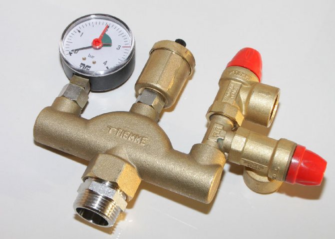
air valve for heating. The most common automatic venting device. It is intended only for vertical installation - in the sense that if you suddenly decide to use it for a battery, then you will additionally need a corner at 90 degrees. The optimal area of their application is pipelines, or rather their upper points, where, according to all the laws of physics, the air formed in heating rushes. If it were not for such devices, then it would be very inconvenient to discharge air at the highest points of heating systems. In addition, some heating system equipment is equipped with automatic dumpers with straight connecting pipes. For example, the automatic air valve is an integral part of the boiler safety group, which also includes a pressure gauge and an explosion valve. Air vents are also equipped with indirect heating boilers and other equipment, at the top of which there is a possibility of air accumulation.
Valve on radiator for air relief
Safety valve
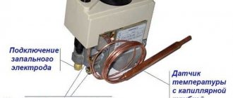
In most models of modern boilers, manufacturers provide a safety system, the "key figure" of which is the safety fittings included directly in the boiler heat exchanger or in its piping.
The purpose of the safety valve in the heating system is to prevent the pressure in the system from increasing above the permissible level, which can lead to: destruction of pipes and their connections; leaks; explosion of boiler equipment The design of this type of valve is simple and unpretentious.
The device consists of a brass body, which houses a spring-loaded closing diaphragm connected to a stem. Spring resilience is the main factor that
keeps the diaphragm in the locked position. The adjusting handle adjusts the compression force of the spring.
When the pressure on the diaphragm is higher than the set one, the spring is compressed, it opens and the pressure is released through the side hole. When the pressure in the system cannot overcome the elasticity of the spring, the diaphragm will return to its original position.
Tip: Purchase a safety device with pressure regulation from 1.5 to 3.5 bar. Most models of solid fuel boiler equipment fall into this range.
Air vent
Air congestion. As a rule, there are several reasons for their appearance:
- boiling of the coolant;
- high air content in the coolant, which is automatically added directly from the water supply;
- As a result of air leaks through leaking connections.
The result of air locks is uneven heating of radiators and oxidation of the inner surfaces of the CO metal elements. The air relief valve from the heating system is designed to remove air from the system in automatic mode.
Structurally, the air vent is a hollow cylinder made of non-ferrous metal, in which a float is located, connected by a lever with a needle valve, which in the open position connects the air vent chamber to the atmosphere.
In working condition, the inner chamber of the device is filled with a coolant, the float is raised, and the needle valve is closed. If air enters, which rises to the upper point of the device, the coolant cannot rise in the chamber to the nominal level, and therefore, the float is lowered, the device operates in the exhaust mode. After the air is released, the coolant rises in the chamber of this kind of fittings to the nominal level, and the float takes its regular place.
Non-return valve
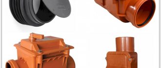
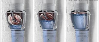
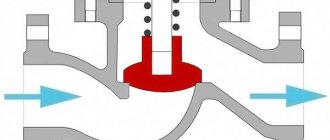
In gravity CO, there are conditions under which the coolant can change the direction of movement. This threatens to damage the heat exchanger of the heat generator due to overheating. The same can happen in sufficiently complex COs with forced movement of the coolant, when water, through the bypass pipe of the pumping unit, enters the boiler back into the boiler. The mechanism of action of the check valve in the heating system is quite simple: it passes the coolant only in one direction, blocking it when moving back.
There are several types of this kind of fittings, which are classified according to the design of the locking device:
- disc-shaped;
- ball;
- petal;
- bivalve.
As it is already clear from the name, in the first type, a steel spring-loaded disk (plate), connected to the stem, acts as a locking device. In a ball valve, a plastic ball acts as a shutter. Moving "in the right" direction, the coolant pushes the ball through the channel in the body or under the cover of the device. As soon as the circulation of water stops or the direction of its movement changes, the ball, under the influence of gravity, takes its original position and blocks the movement of the coolant.
In the petal, the locking device is a spring-loaded cover, which is lowered when the direction of water in CO changes under the action of natural gravity. The bivalve element is installed (as a rule) on large diameter pipes. The principle of their work does not differ from the petal one. Structurally, in such an armature, instead of one petal, spring-loaded from above, two spring-loaded flaps are installed. These devices are designed to regulate temperature, pressure, and stabilize the work of CO.
Balancing valve
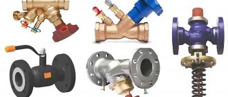
Any CO requires hydraulic adjustment, in other words - balancing. It is carried out in various ways: by correctly selected pipe diameters, washers, with different flow cross-sections, etc. The most effective and at the same time simple element of setting up the operation of CO is a balancing valve for the heating system.
The purpose of this device is to provide the required volume of coolant and amount of heat for each branch, circuit and radiator.
The valve is a conventional valve, but with two fittings installed in its brass body, which make it possible to connect measuring equipment (manometers) or a capillary tube with an automatic pressure regulator.
Principle of operation
balancing valve for the heating system is as follows: Turns the adjusting knob to achieve a strictly defined flow rate of the heat carrier.This is done by measuring the pressure at each nozzle, after which, according to the diagram (usually supplied by the manufacturer to the device), the number of turns of the adjusting knob is determined to achieve the desired water flow rate for each CO circuit. Manual balancing regulators are installed on circuits with up to 5 radiators. On branches with a large number of heating devices - automatic.
Bypass valve
This is another CO element designed to equalize the pressure in the system. The principle of operation of the bypass valve of the heating system is similar to the safety one, but there is one difference: if the safety element bleeds off excess coolant from the system, then the bypass valve returns it to the return line past the heating circuit.
The design of this device is also identical to the safety elements: a spring with adjustable elasticity, a shut-off diaphragm with a stem in a bronze body. The flywheel adjusts the pressure at which this device is triggered, the membrane opens the passage for the coolant. When the pressure in CO stabilizes, the membrane returns to its original place.
Based on materials from the sites: ventilationpro.ru, stroisovety.org
Air-vapor valve for the cooling system of an internal combustion engine
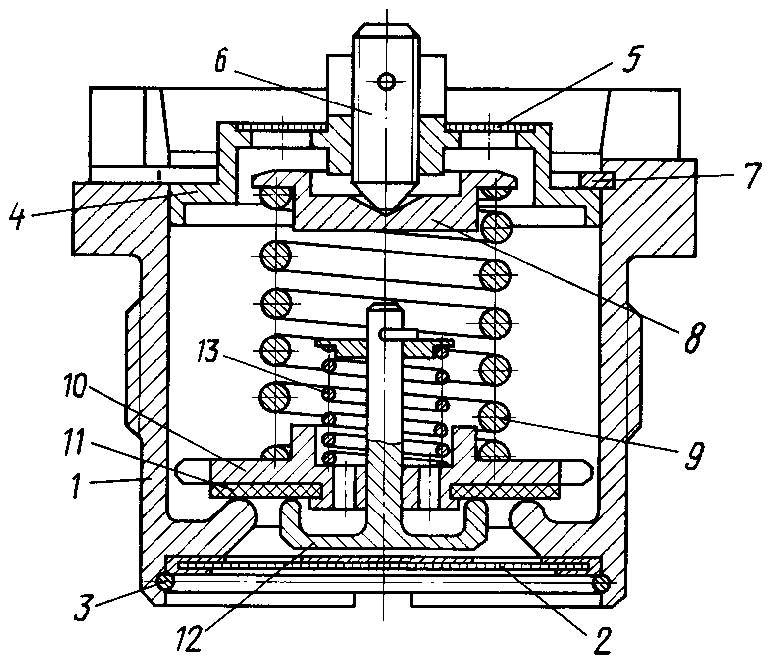
The invention relates to the field of armored vehicles and is intended for use in a liquid cooling system of an internal combustion engine of a tank. The air-vapor valve of the cooling system of an internal combustion engine contains a housing with a cover. Spring-loaded air and steam valves are located inside the housing. A through threaded hole is made in the valve cover along the axis. The valve is equipped with a plate installed under the cover on the end of the spring of the steam valve, and an adjusting screw installed in a threaded through hole made axially in the valve cover. A conical recess is made in the upper part of the plate, interacting with the end of the adjusting screw. The technical result of the invention is to increase the reliability of the steam valve and improve the operating conditions by ensuring the adjustment of the actuation pressure of the steam valve without disassembling the steam-air valve. 1 ill.
The invention relates to the field of armored vehicles and can be used in a liquid cooling system of an internal combustion engine (ICE) of a tank.
The air-vapor valve (PVK) is installed in the expansion tank of the internal combustion engine cooling system, serves to maintain a certain pressure of the coolant vapor and air in the system, i.e. protects the components of the cooling system and the internal combustion engine from overloading at excessive pressure of the engine overheating or vacuum during its cooling. Known PVC, in the body of which are installed spring-loaded steam and air valves, adjustable by threaded connections. Access to the adjustable nuts is closed by a stopper. The disadvantage of this design is the difficulty in adjusting the set pressure of the steam valve. The stopper must be removed to access the adjusting nut. In addition, the valve is not triggered at constant pressure due to the fact that the steam valve moves in two pilot holes, one of which is located in the PVC housing, and the other in the air valve. The pilot holes can be misaligned. During operation, the upper guide hole of the PVCC body can become clogged with fine dust, and scale forms in the hole of the air valve. As a result of this, the steam valve is seized and its operation occurs at a higher pressure in the cooling system than is required by the requirements.At the same time, the units and parts of the cooling system and the internal combustion engine are overloaded and may fail. The tank cooling system and internal combustion engines operate with high thermal intensity. The permissible temperature of the coolant is negotiated within certain limits, therefore the pressure in the cooling system is also allowed within certain limits. The PVK is regulated to operate at a certain pressure, thereby providing a given permissible temperature of the coolant. The disadvantage of the prototype is that a large variation in the response pressure of the PVC is obtained from - due to the fact that the upper end of the steam spring is pressed by the lid. When assembling the PVC, by pressing on the cover, the spring is compressed, and the cover is locked with a ring. The parallelism of the ends of the spring and the alignment of the hole in the cover for the end of the spring and the shoulder on the steam valve affect the opening pressure of the valve. At the next disassembly - assembly for maintenance, the spring takes a non-fixed position and the response pressure differs from the initially adjusted more than the valve response tolerance. To regulate the response pressure, it is again necessary to disassemble the PVK and achieve a predetermined value of the response pressure. The aim of the present invention is to increase the reliability of the PVK operation and improve the operating conditions. and air valves, a boss with a threaded hole is made in the valve cover along the axis, in which an adjusting screw with a tapered end is installed. A disc is freely installed under the cover on the upper end of the steam valve spring. A conical recess is made in the top of the plate in the center, against which the end face of the adjusting screw abuts. Comparative analysis with the prototype shows that the proposed PVCC is distinguished by the presence of a central threaded hole in the valve cover, in which an adjusting screw is installed, interacting with the conical recess of the plate, freely installed on the upper end of the steam valve spring. Thus, the claimed air-steam valve meets the criterion of the invention "novelty". Comparison of the claimed invention not only with the prototype, but also with other technical solutions in this field of technology, did not reveal in them the features that distinguish the claimed solution from the prototype, which allows us to conclude that according to the criterion "significant differences." PVCL from sediments and impurities contained in the coolant. The mesh is fixed with a retaining ring 3. In the upper part of the body there is a cover 4 with holes protected by a mesh 5 for free passage of air and vapor-air mixture and a through threaded hole in the center for installing an adjusting screw 6. The cover is fixed against vertical movement by a retaining ring 7 and is an easily removable element during maintenance of PVC. A plate 8 is freely located under the cover, compressed by a spring 9 of a steam valve 10, a rubber gasket 11 and an air valve 12 with a spring 13. The plate 8 has a conical recess into which the end of the screw 6 enters. The device and adjustment of the air valve is carried out as in the prototype, namely, due to the selected spring 13, which presses the air valve 12 against the gasket 11. The large interval of allowable vacuum pressure in the cooling system does not require additional adjustment of the air valve.The steam valve is adjusted by pressing the spring 9 through the plate 8 with the adjusting screw 6 until the required actuation pressure of the valve is provided according to the technical requirements, followed by reliable locking of the screw. The PVK is installed in the expansion tank of the internal combustion engine cooling system through a gasket.If the maximum permissible temperature of the coolant in the engine cooling system is exceeded and the maximum pressure in the expansion tank, to which the steam valve is adjusted, is reached, it is triggered. Namely, before the compression force of the spring 9, the steam valve 10 opens and the vapor-air mixture is ejected through the gaps between the steam valve and the housing 1 into the openings of the cover 4 and into the engine-transmission compartment of the tank. Thus, the components of the cooling system and the engine are protected from overloads at excessive pressure from overheating. Due to the fact that in the proposed PVK, a plate is freely installed on the upper end of the steam valve spring, in the central part of which a cone drilling is made, and an adjusting screw is installed in the cover, the possibility of adjusting the actuation of the steam valve without disassembling the PVK is provided. This improved the conditions for servicing the PVC during operation. Due to the fact that the compression force of the spring of the steam valve by the adjusting screw is directed in the center, the influence of the mutual position of the parts on the accuracy of the operation of the steam valve is excluded. In this case, the accuracy of the operation of the steam valve is increased by almost 20 times. In addition, after partial assembly-disassembly under operating conditions, adjustment of the PVC is not required.
Claim
A steam-air valve for the cooling system of an internal combustion engine, comprising a housing with a lid, spring-loaded air and steam valves located inside the housing, characterized in that, in order to increase the reliability of the steam valve and improve operating conditions by adjusting the actuation pressure of the steam valve without disassembling the steam-air valve, a through threaded hole is made in the valve cover along the axis, it is equipped with a plate installed under the cover on the end of the steam valve spring, and an adjusting screw installed in a threaded through hole made axially in the valve cover, while a conical recess is made in the upper part of the plate, interacting with the end of the adjusting screw.
DRAWINGS
