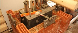
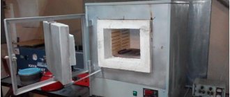
Brick making techniques
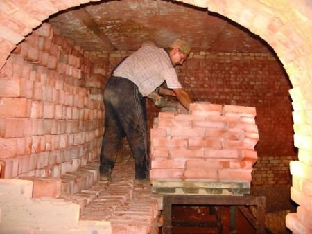
How does brick firing work?
There are two common methods for making bricks. The first is semi-dry and dry pressing. The plastic molding method is the second brick making method. The difference lies in the different amount of moisture contained in the raw material in both production methods. It should be noted that the second manufacturing method is most widely used.
Plastic molded bricks can be hollow or solid. The principle of production of both types of bricks is the same, the difference is that clay is more thoroughly prepared for hollow bricks.
The following stages of brick making can be distinguished:
- Preparation of raw materials
- Bar molding
- Drying of raw bricks
- Burning
It should be noted that each stage is characterized by careful observance of the parameters. For example, in order to carry out the firing, which is the final stage of production, all technical requirements must be observed. Brick firing technology implies compliance with both temperature and time conditions. Otherwise, a defective product is inevitable.
Tunnel oven
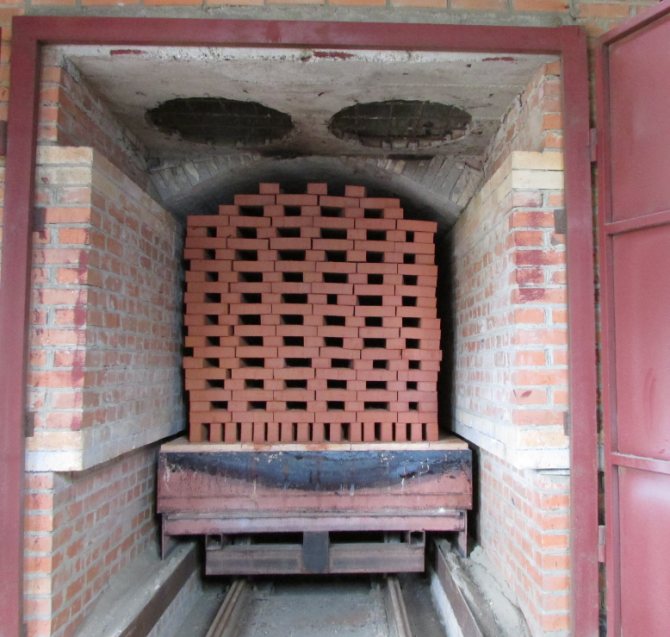
Most brick factories producing single solid bricks and ceramic stones are equipped with furnaces of this type. They represent a tunnel through which trolleys or a conveyor belt with raw materials move. Their working space can have one or two channels located in a straight line or having a closed, annular shape.

Principle of operation
In contrast to ring plants, here everything happens the other way around: the material moves through the remaining stationary, clearly demarcated zones of heating, annealing and cooling. The material moves sequentially from zone to zone. In such a furnace, there is only one entrance and one discharge area. They are located at opposite ends of the tunnel and are equipped with mechanisms that hermetically seal the inner space of the furnace during loading and unloading of material. Sealing occurs automatically, which avoids excessive consumption of the coolant. The space above the floor, under the conveyor or the bottom of the trolleys also does not warm up, as it is fenced off with a sand gate.
Natural gas is used as a heat carrier. Sometimes they are modified to run on fuel oil, diesel fuel, heating oil, and electrical energy. Combination of options is possible.
The oven works around the clock. Gas burners direct flares of burning gas onto the brick mass directly (in open furnaces) or through protective screens (in muffle furnaces). Fans and smoke catchers are installed along the entire channel, directing the required amount of heated air and flue gases to the required zones of the furnace through special circulation channels. These devices work independently of each other and are remotely controlled by the operator. The furnace is loaded manually by workers, and the unloading is mechanized.
The firing technology is automated as much as possible. Special computer programs with the help of numerous sensors monitor the technological process and give control commands:
- temperature regime in all zones.
- air pressure.
- the speed of the trolleys.
The choice of the operating mode of the furnace is carried out automatically and depends on the initial parameters of the raw brick (type, shape, size, moisture level, type of cage).The controller stores all possible modes in memory and selects the most optimal one. Quality control of finished products is also automated. The duration of the technological cycle for solid products is from 36 to 40 hours, hollow stones are ready in a day.
izkirpicha.com
How ceramic bricks are fired
Raw brick contains from 8% to 12% moisture, enters the kiln for firing, where it is initially dried. Then the temperature increases to a level of 500-800 ° C, at which dehydration of minerals from the clay occurs. Because of this, the product shrinks. At temperatures above 200 ° C, the release of volatile organic impurities and additives is observed.
At this stage, the brick firing temperature rises at a rate of 300-350 ° C / h. The temperature is kept constant until the carbon is burned out. And only after that, the temperature is raised to 800 ° C. Exposure to such temperatures causes the product to change its structure. For some time, they maintain the maximum temperature for uniform heating of the brick. Then the temperature starts to decrease gradually.
The brick firing time can reach from 6 hours to 48 hours. While this process is taking place, the brick structurally changes repeatedly. If the production technology is observed, the output is a product with high strength and water-resistant qualities. It is characterized by sound and heat insulation properties, as well as resistance to various temperature conditions.
We recommend reading:
What to buy equipment for the production of Lego bricks in Russia?
Choosing a sand-lime brick machine.
What is this process and features of the technology
Heat treatment of clay building materials under the influence of high temperatures is called firing. This is the final stage in the production of brick blocks. The firing technology includes 3 stages:
- Warming up.
- Burning.
- Cooling.
At the first stage, the brick is heated to a temperature of 120 degrees, in order to evaporate water from it. Then, to burn out impurities of organic origin and the final withdrawal of the liquid, it is heated to 600 gr. At the next stage, the brick firing temperature is 920-980 degrees. At the same time, the clay begins to shrink, strength is acquired. Under conditions of constant maximum temperature, the brick block hardens and languishes for some time. At the final stage, the resulting clay building material is cooled. If during the heat treatment there was no violation of the technology, the color of the block will be orange-red, and the structure will be uniform. To obtain glazed bricks, re-firing is required.
In order to end up with a durable and high-quality fired brick without cracks, strict temperature control is required during heat treatment.
Types of brick kilns
Various kilns are used during the firing phase. Which equipment for brick firing to use in production depends on various factors. The brick kiln is both a process equipment and a thermodynamic open system at the same time. Constant thermal processes take place in it.
Ring furnace
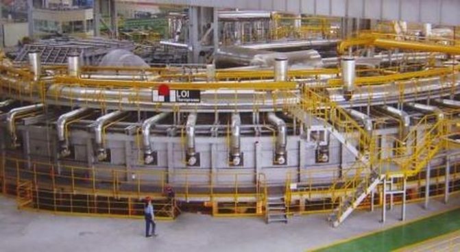

Ring brick kiln
One type of brick kiln is ring kiln. It is these vaulted furnaces that are most widely used in brick production. If an annular brick kiln is not installed in a production plant, then it is advisable to use it without a roof. The cost of construction is slightly more expensive compared to floor-standing ovens, however, their maintenance is much more convenient and easier.
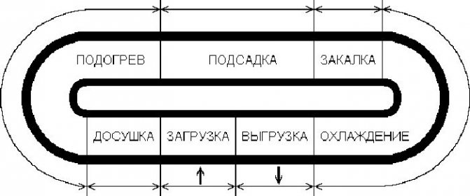

Diagram of a ring kiln for firing bricks
Firing bricks in an annular kiln gives a result in quality that is significantly higher than in a floor kiln, and fuel is consumed several times less per 1,000 fired bricks.Another advantage of these stoves is that they can be fired with different types of fuel. All this influenced the widespread use of ring furnaces.
Tunnel oven
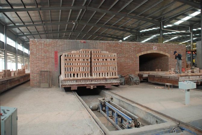
Tunnel ovens are replacing ring ovens, gradually replacing them. More and more large brick factories are using them in their production. In tunnel kilns, bricks move on special trolleys, in contrast to circular ones, where the brick is stationary, and various temperature regimes are passed through it. The tunnel kiln for firing bricks is easier to maintain, because the unloading and loading of a batch of bricks takes place outside the kiln, where there are acceptable temperature conditions for the personnel. In addition, it is much easier to mechanize processes in front of the work area than in it. The kiln is a tunnel with rails inside. Firing bricks in a tunnel kiln takes place on trolleys, which stand one by one along the entire length of the tunnel. After a certain time interval, a new trolley with raw bricks enters the tunnel, and a trolley with ready-made products leaves the back of the tunnel.

Tunnel brick kiln
The ovens can be fitted with a variety of heat sources. It is possible to heat the kilns for roasting with coal, oil. An electric furnace or gas burners are installed. Convenience of service and economic benefit of production depend on the type of the selected heat source. If a gas kiln for firing bricks is chosen for production, then regardless of whether it is an annular or tunnel kiln, the result will be of high quality only if the technological parameters are observed.
You might be interested in:
Choosing a press for the production of Lego bricks.
What kind of clay is suitable for brick making?
Furnace types
For the firing of ceramics and the production of fired, including ceramic bricks, special furnaces are used. They are of 2 types:
- tunnel;
- ring.
Tunnel oven

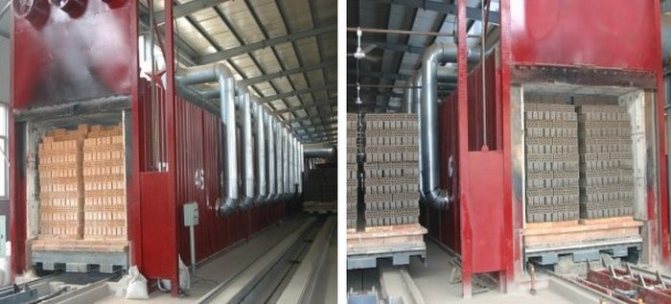
The tunnel-type device is a long, tunnel-like gas kiln for firing bricks. Inside there are 3 chambers and rails. Metal trolleys move along them with the help of automatic pushers. Before entering the furnace, they are loaded with unfired brick. The entrance and exit are hermetically sealed. After drying in 1 chamber, brick blocks are moved to 2 for firing. It is provided by gas burners that constantly maintain the temperature at the level of 920-980 degrees. Then the brick enters the third zone with a lower temperature, where it is cooled. After the end of the mode, the pushers roll the trolleys out of the furnace and the brick blocks cool completely outside of it.
Ring furnace
Devices of this type consist of many adjacent sections in the form of a ring. Each of them has a window for loading and unloading material, as well as its own heating source. The ring kiln ensures the continuity of the firing process. Thus, a batch of brick blocks goes through all stages of heat treatment, being in the same compartment. The adjacent chamber promotes heating, the blocks are calcined at the expense of their own fuel, and cooling is provided by the temperature of the next section.
We fire bricks at home
If you step aside from large volumes of production in brick factories and think about smaller quantities of production, then it is possible to organize the firing of ceramic bricks at home. In order to burn a brick in small quantities, you will need an ordinary metal barrel with a capacity of 200 to 250 liters. Previously, it is necessary to cut out the bottoms in it on both sides.
Firing can also be carried out using a fire.To do this, you need to dig a hole half a meter deep, and install a barrel above it, raised above the edge of the hole at a height of about 20 cm.In a place where there is no lower bottom, it is necessary to adapt supports in the form of rods or a metal grate. This is necessary so that there is a basis for storing bricks inside the barrel.
After filling the barrel with bricks, cover its upper part with a lid in order to minimize heat loss. Firing lasts approximately 20 hours, depending on the nature of the clay composition used in the brick. It is possible to fire bricks with gas, but as mentioned above, economic profitability depends on the type of fuel.
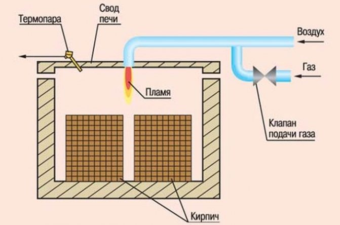

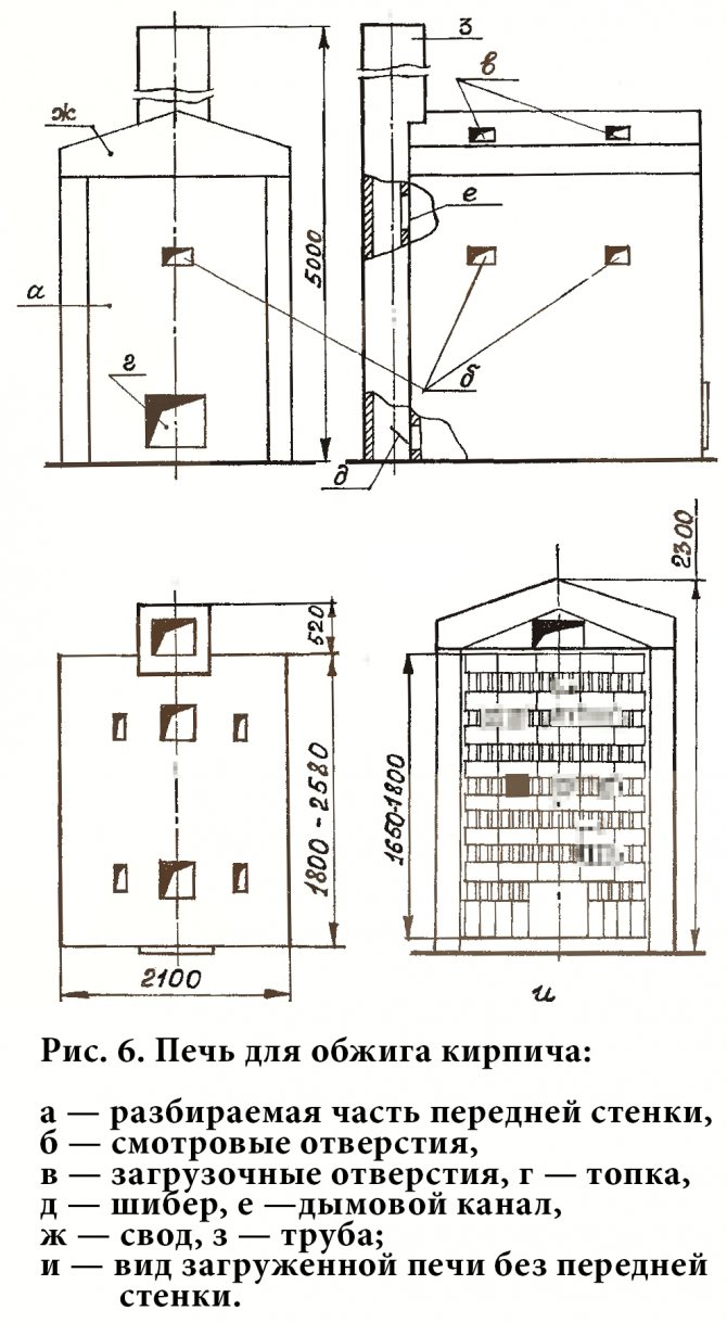
Diagram of a furnace for firing bricks with gas
We recommend these articles:
What is better to buy matrixes for Lego bricks?
How to choose a manual brick press?
Features of the multistage process of firing ceramic bricks in a tunnel kiln
The increase in the pace of construction and competition between manufacturers of building materials in the market of Uzbekistan necessitates an increase in the quantity and improvement of the quality of building bricks. The solution to this problem can be achieved by improving the control system for the technological processes of drying, firing, and the production cycle for producing bricks. It is during the passage of firing and drying that the properties of the product are formed, which determine the quality of the product. It includes both measured mechanical and hydrophysical indicators (strength, frost resistance and water absorption) and visual defects (cracks, melting, burnout). Roasting and drying should be considered as multistage heat and mass transfer processes, which are accompanied by phase and chemical transformations of raw materials.
The technological process, the production of bricks is carried out mainly in tunnel ovens, is characterized by the distribution of the temperature of the gaseous medium (temperature field) and the load of products, the instability of the properties of the semi-finished product, as well as the impossibility of controlling the properties of the ceramic material during its long (up to 120 hours) stay in the furnace, in the mode real time. The lack of substantiated recommendations for choosing the optimal temperature field, taking into account the quality indicators of the finished product, changes in the properties of input material flows, the state of technological equipment, necessitate the creation of a mathematical model of the process, its optimization and improvement of the automated control system.
Creation of a control system for the process of firing ceramic bricks in a tunnel kiln, which contributes to improving the quality of finished products by preventing emergencies, introducing pre-emptive actions obtained as a result of predicting the characteristics of products and determining the optimal temperature field in conditions of instability of a semi-finished product.
A tunnel kiln is a continuous heating installation, in which the charge of products moves along a long rectilinear firing channel towards the heat carrier. The movement of products through the furnace occurs due to pushing a new car into the burning channel after a certain time, which is called the pushing interval. The mechanism that pushes the cars is called a pusher. At the entrance and exit, the furnace is equipped with mechanical curtains to eliminate air suction into the firing channel. Between the entrance curtain and the heating zone, there is a prechamber one carriage length. This design feature of the furnace is designed to prevent the violation of the temperature regime of the furnace when pushing in new products. The car is first pushed into the prechamber, while the curtain between it and the heating zone is lowered. After closing the inlet, the outlet curtain of the prechamber is raised and the car is pushed directly into the furnace channel.
The kiln channel is conventionally divided into positions, the length of which is equal to the length of the kiln car, that is, the number of positions is equal to the number of cars being fired.
When choosing the type of charge, the design and size of the firing channel, the type of products, the fuel and the method of its combustion, and the design of the burner equipment are taken into account.
The structural diagram of the production of ceramic bricks can be represented as a chain of interconnected technological processes (stages). [1] Fig. one.
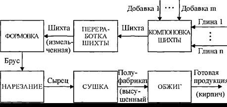

Fig. 1. Block diagram of the production of ceramic bricks
The layout of the charge. The raw material components of the charge (mixtures of clays and impurities, mixed in certain ratios) are delivered to the clay storage, from where they are moved with a grab crane to the hoppers of individual box feeders, which carry out uniform feeding and volumetric dosing of the components of the charge. The dosage is regulated by the lifting height of the gates and the speed of the feeder belts, which are calculated in a certain way.
The metered components of the charge are fed to the knife crusher, where they are pre-crushed. Then the charge goes through the processing stage, which takes place in the corresponding workshop. It contains runners of wet grinding, roller mills of coarse and fine grinding, clay mixers. In the runners of wet grinding, grinding, mixing, grinding, moistening the charge with water, crushing and pushing it through plates with holes installed in the grinding zone takes place. The maximum particle size of the batch after the runners is 50mm. The pan mixer, installed under the runners, feeds the charge to a belt conveyor, which delivers it to the roller mill. It carries out the primary grinding and grinding of the charge. As a result of this processing, the particle size does not exceed 3-5 mm. After the initial grinding, the charge is fed by a belt conveyor to the second roller mill. The processes taking place in it are similar to those in the previous apparatus, but the maximum size of the charge particles is already 1mm. [2]
After such processing, the charge enters the clay mixture. Intensive mixing, homogenization and additional moistening of the charge to a predetermined molding moisture takes place here. In winter, if necessary, the ceramic mass is heated with steam. In the chamber of the clay mixer, the charge is compacted and pressed through the holes in the grate. Then it is fed into the feeder, and from there - for molding into a worm vacuum press.
Forming. The ceramic mass moves into the trough of the block, in which it is steamed and pushed by the blades into the transitional part. In it, the blades, replaced by a system of worms, push the prepared mass through the tapered outlet holes. The knives cut the mass into plates, which are fed into the vacuum chamber for deaeration. From there, through the feed rolls, they enter the worm chamber, where a set of worms are pushed through the mouthpiece mounted on the press head. Thus, a bar is obtained in the form of a continuous strip. [3]
Cutting. Inside the mouthpiece, cores are mounted on a special bracket, which form through holes in the bar. A continuous strip of timber is cut into raw materials - products that are stacked on drying trolleys and fed into tunnel dryers.
Drying. The coolant is the air coming from the cooling zone of the tunnel kiln. Longitudinal circulation of the coolant in the dryer systems is provided by exhaust fans that remove the spent coolant. The regulation of its quantity is carried out with the help of dampers mounted at the ceiling of the dryer. Part of the coolant is taken from the dryer by mobile fans, which circulate it in the transverse direction of the unit's channels, evenly blowing the raw material.Drying is designed to remove excess moisture from the raw material, which is indicated by the relative residual moisture content of the raw material at the outlet of the unit. According to the technological regulations of production, the value of this variable is in the range of 1.5-3%. [four]
Trolleys with dried raw material are pulled out of the dryer and sent to the transshipment base. Here the raw material is transferred to the kiln cars. The structure that is obtained as a result of this operation is called the brick setting. The loaded cars are moved to the kiln, where they are fired.
The firing process is the last and most important in the production of bricks, since it is during this process that the properties of the products that define the concept of "quality" are finally formed. It includes both measured mechanical and hydrophysical indicators (strength, frost resistance and water absorption, etc.) and visual defects (cracks, melting, burnout, etc.).
The firing cycle consists of periods of heating, holding in the area of high temperature (sintering) and cooling, each of these periods is characterized by certain physicochemical processes that take place in the ceramic mass. The final properties of the products depend on the correctness of these processes, for which it is necessary to adhere to clear requirements for the temperature regime and the duration of firing at each position of the furnace.
Thus, the tunnel kiln is conventionally divided into 3 zones: heating, roasting and cooling. The heating zone is intended for the final drying of products and their heating to the temperature of the gaseous medium of the firing zone. The heating zone consists of three sections. On the first one, located after the prechamber, drying of the raw material begins on the newly introduced kiln cars with the heat of the exhaust flue gases, which have already passed through other sections of this zone (Fig. 1). In the second section, on both sides of the channel, there are openings for exhausting flue gases from the furnace. At the third stage, the products are heated with flue gases and products of fuel combustion, which come from the firing zone.
The firing zone is divided into two sections: small and large fire. In the small fire area, the semi-finished product is intensively heated by the heat of the flue gases that come from the large fire area, as well as by the heat of the fuel burned in the burners of this area. The burners are grouped into burner groups located at each position of the firing zone. In a zone of high fire, products are kept at the maximum temperature.
The cooling zone is conventionally divided into fast and final cooling zones. External air is supplied to the cooling zone through an opening in the roof and channels in the furnace outlet by a specially installed fan. Air supplied to the tunnel from the environment moves along it, cooling the brick. Holes are made in both walls of the cooling zone, through which heated air is removed from the firing channel into the heating channel, and is forced into the dryer.
Literature:
- Ladanyuk A.P., Tregub V.G., Kishenko V.D. Management of technological complexes in computer-integrated systems // Problems of Management and Informatics. - 2002. - No. 2.
- Yaroshchuk I.V., Ostapenko Yu.A. Experimental study of bricks firing in a tunnel kiln to create mathematical support for the control system. works of the VIII international. scientific and technical conf. "Mechanical engineering and technosphere at the turn of the XXI century." - Volume Z. - Donetsk: DonSTU, 2001.
- Technological regulations for the production of ceramic stones and bricks at the plant of ceramic wall materials. Approved. director of the building materials plant. - K., 1994 .-- 63 p.
- Machine-building ceramics / Garshin A.P., Gropyanov V.M., Zaitsev G.P., Semenov S.S. - SPb: GTU, 1997. - 726 p.
What you need to buy a brick kiln
If you think about starting a ceramic brick business, then you need to consider more serious options than burning bonfires in the yard. If you have already decided to buy a mini brick kiln, then you need to choose the most suitable option. It is worth thinking about what volumes are planned to be produced, because each furnace has its own capacity.
Also an important point is to choose a stove with a suitable type of fuel, because in our time of rapid changes in energy prices, this issue requires serious attention. It is worth considering the feasibility of buying a kiln with a higher capacity if there are plans to increase production.
When the questions on the main characteristics are resolved, it is necessary to choose the appropriate version of the model and start looking for options for a bargain purchase. The price of a brick kiln from different dealers and sellers may fluctuate, so there is no need to rush. Most of the representatives who sell these products do not put prices in the public domain, so you have to work hard to find a great deal. But the result of the savings can pleasantly exceed all expectations!
A method of firing bricks and a device for its implementation
The invention relates to the production of bricks and building ceramics. EFFECT: increasing the intensity of the process, ensuring the uniformity of firing and improving the quality of the resulting products. The brick setting is formed by sequentially placing one item on top of another to form two opposite faces of the pillar with the solid surfaces of the items. The pillars of the products are placed with the formation of gaps between the aforementioned edges of the pillars sufficient for the free movement of the coolant. Bricks are fired in a shaft kiln. In the firing channel of the furnace, vertical guides are mounted, arranged in groups in the form of a set of guide channels spaced apart from one another. The sources of the coolant are placed in the gaps between the guide channels and the coolant is fed into the gaps between the die edges of the products. 2 sec. and 12 p.p. f-ly, 10 ill.
The technical field to which the invention relates The invention relates to the building materials industry and can be used in the production of bricks and some other ceramic products, namely in the technological process of firing. The invention is applicable to all types of bricks and ceramic stones having the shape of a rectangular parallelepiped, as well as a shape close to it.
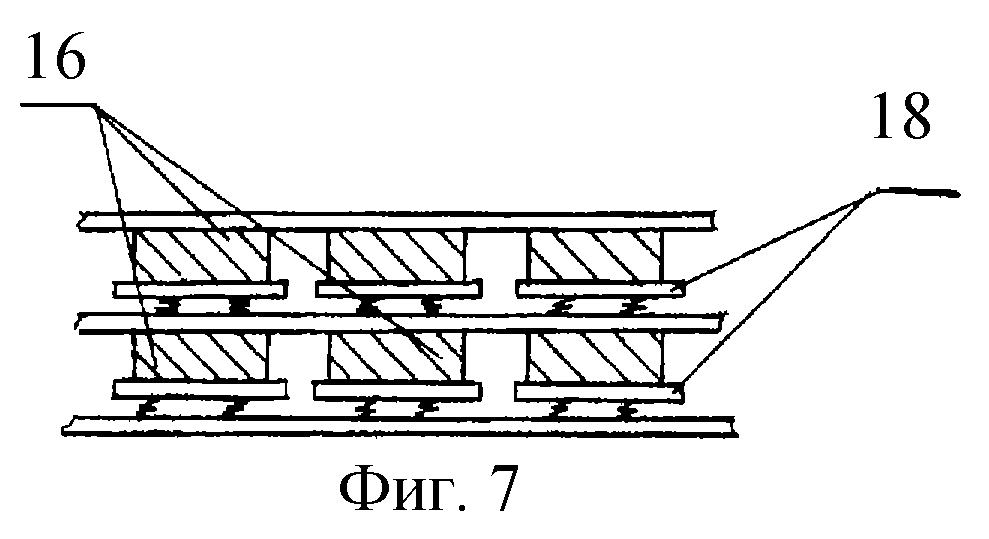
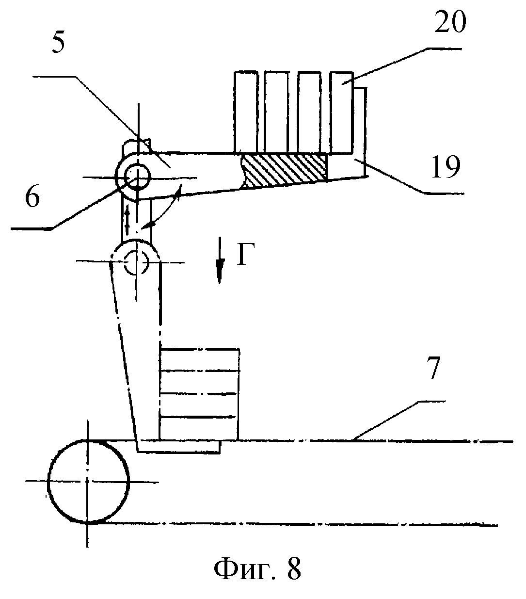
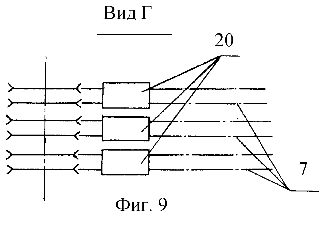
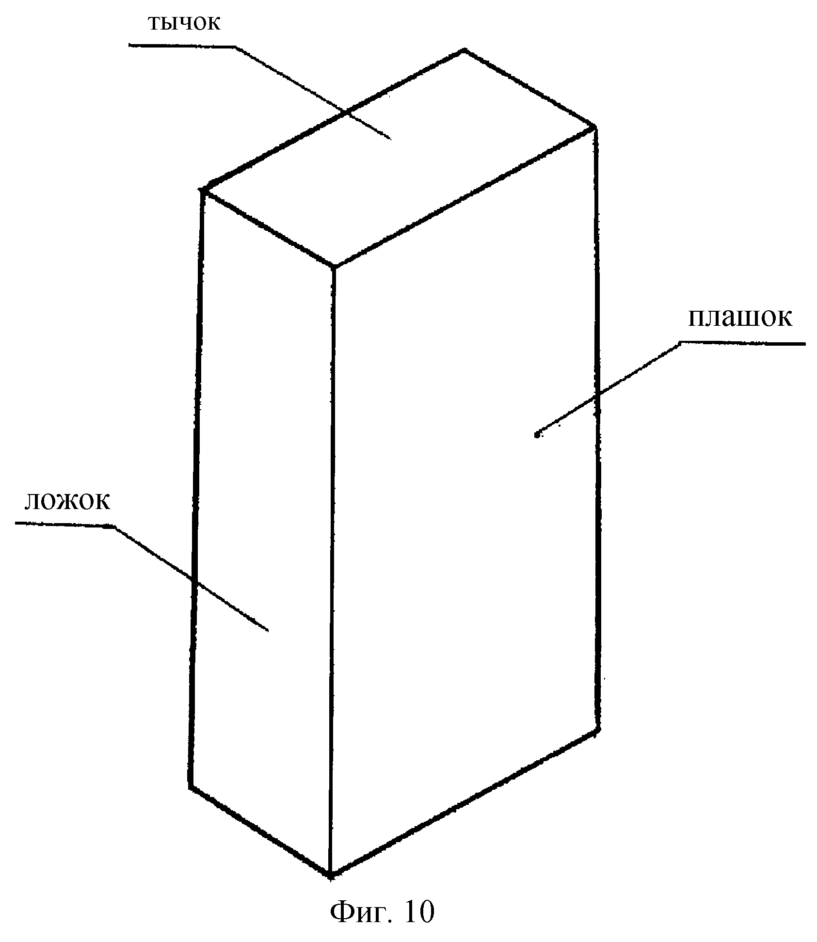
BACKGROUND ART The most widely known methods for firing bricks in ring and tunnel kilns. However, the disadvantage of such furnaces is the uneven firing of stacked bricks, cumbersome production, heat losses, the presence of special carts for moving the load of products. Recently, vertical continuous furnaces have become widespread: shaft and slot, with moving material and stationary technological zones. The technological process in vertical furnaces is directed from top to bottom, which made it possible to use the movement of products under their own weight and exclude special vehicles for moving products through the furnace. In addition, the vertical design of the kiln made it possible to bring heat sources closer to the fired products, which led to an increase in the thermal efficiency of the process and a decrease in firing time. Thus, vertical furnaces are less material-consuming, and the method of firing in such furnaces is faster, more productive and economical. There is a known method of firing ceramic products (patent for invention 2110027, RF, class F 27 B 1/00, F 27 B 9 / 14, publ. 04/27/1998), in which the products are sequentially fed into the furnace by a pusher from the press.Products are moved along a spiral path, which is set by a spiral single-turn roller table, from top to bottom through the heating, firing and cooling zones. The movement channel is formed by a cylindrical gap between the coaxially located furnace walls (inner and outer). The heating of bricks in the firing zone is carried out by means of gas burners located in the outer wall of the kiln. This method provides high productivity of the process, but requires special equipment. In addition, the cage of bricks, which is products laid on top of each other die on die (i.e. bed on bed), does not provide uniform access of the heat carrier to the entire surface of the product, which leads to uneven firing of the product in its volume. ceramic products in a vertical furnace (patent for invention 2098384, RU, class C 04 B 33/32, F 27 B1 / 00, publ. 10.12.1997), including the supply of the coolant into the cage in the horizontal direction by several formed layer-by-layer and directed towards each other by streams converging in the center of the cage, moving one step up and then diverging from the center in opposite directions. In this case, the packing of products is performed in such a way that alternations in height of rows of bricks installed on the spoon edge and on the die take place in it. The layout of the cage of bricks installed on the spoon edge does not change and is repeated through a row in height. It provides through channels for the passage of the coolant. The setting of the rows of bricks laid on the block is changing. In the first version, there is one channel for the passage of the coolant, and it passes through the center of the row, dividing the row into two equal parts. In the second version, two side channels are formed, which are located between the charge and the opposite walls of the furnace, to which the furnaces are adjacent. The above-mentioned layer-by-layer movement of the coolant flows through the channels formed by a certain arrangement of products in the rows is repeated many times, as is the alternation of rows in the cage. This ensures an even distribution of the coolant and air for cooling products along the stack height. Raw bricks are loaded manually or by an automatic machine. The movement of the cage can be continuous or periodic after a certain period of time. The whole cage of bricks is held and moved by a special device. The advantage of the above invention is to improve the quality of products by ensuring the uniformity of firing, however, the cage of products has a rather complex structure and requires a special device for moving. The closest to the claimed invention is a method of firing wall ceramic products in a vertical furnace (patent for invention 2031340, RF, class F 27 B 1/00, publ. 03/20/1995, bulletin 8), which is a technological cycle that includes the loading of products by layer-by-layer loading mechanism from the top of the furnace, synchronous movement down one row the entire charge along the firing channel and layer-by-layer batch unloading of finished products from the bottom of the body. The products are loaded in the form of pillars with a section of 250x250. When firing products in nozzles, fuel is burned, and through the gas distribution devices, the resulting coolant leaves the gaps and washes the cage. The cage design plays a decisive role both in the process of heat exchange between the products and the gas flow, and in the spread of heat in the body of the brick. Uneven heating of the product, especially under high-speed firing conditions, leads to the appearance of warpage and deformation of the product, which means a decrease in the quality of the finished product. Consequently, the cage should provide minimal resistance to the movement of gases and air, promote the most uniform distribution of fire over the section of the furnace channel, be stable and at the same time convenient for loading and unloading bricks.The cage is perfect in thermal engineering respect, in which the products are installed so that the maximum possible surface area of the product is freely and evenly washed by the coolant.In the solution according to patent 2031340, each cage column is formed by rows of bricks installed on top of each other with the formation of a section of 250x250, i.e. ... several products in each row of the pillar. In this version of the cage design, there are labyrinthine gaps for the passage of the coolant, which makes it difficult for the coolant to access the products. As a result, the intensity of firing decreases, the time required for sufficient heating of products increases, and, in addition, uniform heating of products inside the cage is not ensured. A vertical furnace for firing ceramic products is known (patent for invention 2023965, RF, class F 27 V 1 / 00, publ. 11/30/1994, bulletin 22), containing vertical firing channels formed by vertical walls made of heat-resistant material, loading and unloading mechanisms located on the furnace frame, respectively, above the inlet and below the outlet sections of the firing channels. In the wall gaps between adjacent sections of the furnace, there are burner devices and channels for supplying air for combustion and cooling products, as well as channels for removing heated air and flue gases. The inlet section of the firing channel is sealed and the firing and cooling zones are separated by rotating spring-loaded dampers. As elements of the mechanism for unloading finished ceramic products, hydraulic cylinders, rotary clamps and a belt conveyor are used. The furnace is classified as a vertical slot oven and has all the advantages of slot ovens listed above. In addition, the furnace implements an effective radiation-convective firing mode, in which the products are heated by the flow of flue gases and thermal radiation from microflakes and the walls of burners. However, the furnace consists of several sections containing one vertical firing channel and separated by walls made of heat-resistant material, which speaks of its high material consumption. The design of the cage in this furnace is a pillar of products stacked orderly on top of each other, which implies the presence of small gaps between the products in the cage, which, in turn, affects the uniformity of heating of the products, and therefore the quality of the products obtained. device adopted a vertical furnace (patent for invention 2031340, RF, class F 27 B 1/00, publ. 03/20/1995, bull. 8), containing a vertical rectangular body with heating, firing and cooling zones, horizontal partitions with windows, loading and unloading devices, gas supply and outlet boxes, load of products, which is placed with a gap in the windows of partitions and is a set of pillars with a section of 250x250 mm. To improve the regulation of the firing process, the furnace is equipped with flowing tanks with water located in the heating and cooling zone and interconnected, and the gas distribution devices of the furnace are made in the form of rectangular pipe sections laid in mutually intersecting horizontal rows, covering the load of products with breaks at the intersection points for the exit The above design features of the furnace make it possible to somewhat improve the uniformity of firing, however, the arrangement of products in the cage in the form of pillars of 250x250 size limits the access of the coolant to the surface of the products inside the column. simultaneous intensification of the firing process. The problem is solved by the fact that in the method of firing bricks in a shaft furnace,including the loading of products from the top of the furnace body with installation on the charge, made in the form of a set of product pillars evenly distributed in the volume of the furnace, synchronous movement of the charge along the burning channel, supply of the coolant to the gaps between the pillars and unloading the finished products from the bottom of the furnace, according to the claimed invention, each column of the charge is formed by sequential installation of one product on another with the formation of two opposite faces of the pillar by the ram surfaces of the products, the pillars of the products are placed in the firing channel with the formation of gaps between the said faces of the pillars sufficient for the free movement of the coolant, and the coolant is supplied in the gaps perpendicular to the faces formed by the ram surfaces of the products .The technical result, namely the uniformity of firing of products, is achieved by increasing the surface free for uniform access of the coolant. Such an increase became possible due to the proposed structure of the product cage. In the claimed method, each brick is installed in such a way that the edges of the product, the largest in surface area, i.e. the dies are freely washed by the coolant. In this case, in one specific case of the implementation of the proposed method, the bricks are installed "with a poke on a poke", and in another - "with a spoon on a spoon". The poke is the smallest face of the brick, therefore, it is preferable to implement the method with the installation of products "poke on a poke". In any case of the implementation of the method, an indispensable condition is the formation of two opposite edges of the column with the solid surfaces of the products, therefore, the solid edges of the product, which have the largest surface area, in any case of the formation of the cage columns remain free and open for access to the coolant. the gaps between the edges of the adjacent pillars formed by the solid surfaces of the products are from 10 to 40 mm, and the gaps between the edges perpendicular to the said ones are from 20 to 80 mm. The gaps are used to ensure free access of the coolant to the products. However, when the size of the gaps between the edges formed by the solid surfaces of the bricks is more than 40 mm and the size is more than 80 mm, for the gaps between the edges perpendicular to the above-mentioned, sufficient temperature stress required for firing is not provided. When the size of the gaps between the dummy surfaces of the bricks is less than 10 mm, it is impossible to place the clamping elements of the fixing mechanism in them to hold the pillars of the products during unloading. The size of the gaps between the edges perpendicular to the die surfaces of the products, less than 20 mm, will not allow placing the sources of thermal energy of firing and gas exhaust devices in them. Upon completion of the movement of the pillars of the products in the firing channel by an amount equal to the size of the product along the height of the column, the products are unloaded. The unloading is carried out in order, and preliminarily, each product is fixed in a row higher than the unloaded one. This goal is also achieved by the fact that a shaft kiln for firing bricks containing a firing channel, a loading device installed above the upper opening of the furnace, a device located under the lower opening of the furnace unloading, including a charge fixing mechanism and a mechanism for lowering and unloading products, sources of thermal energy for firing, located in the firing channel and gas exhaust devices, according to the claimed invention, the furnace is equipped with vertical guides mounted in the firing channel, arranged in groups in the form of a set of guides spaced apart from one another channels freely covering the pillars from successively installed one on top of the other with the formation of two opposite faces of the product pillar by the ram surfaces,wherein the vertical guides of the adjacent guide channels close to the mentioned edges of the pillars are spaced apart from one another with the formation of gaps between the pillars of the articles sufficient for the free movement of the coolant flow, and the thermal energy sources are placed in the gaps perpendicular to the mentioned ones. The introduction of vertical guides into the structure of the device, breaking the working volume of the furnace into a set of vertical guide channels, makes it possible to organize the passage of the fired products sequentially one after another from top to bottom along the firing channel. With this solution, the dimensions of the channels are as close as possible to the dimensions of the transported column of products, but they do not impede the movement of products. Vertical guides can be made in the form of vertical bars made of heat-resistant alloy. The rods are combined into groups that form a guide channel, and are fixed to each other by means of horizontal brackets covering the rods on one or the other side of the channel with alternating male sides along the channel height. The staples have only a point connection with the guides, made, for example, by a welding method, and the welded rods are also alternated. The absence of a rigid connection ensures the mobility of the system, eliminates distortions and deformations possible during high-temperature firing. Vertical guides can be made of thin strips of heat-resistant material, however, in any embodiment, the thickness of the guides should be significantly less than the dimensions of the fired products. This is a necessary condition for ensuring free circulation of the coolant between the items in the charge. Thus, the listed set of essential features allows you to obtain a technical result similar to the method, namely, to ensure uniform firing of items in the furnace. Obtaining the same technical result indicates the unity of the inventive concept connecting the claimed method and device. The guide channels for moving the fired products are spaced apart with the formation of gaps. The size of the gaps between the sides of the guide channels corresponding to the faces of the cage pillars formed by the ram surfaces of the products is from 10 to 40 mm, and the size of the gaps perpendicular to them is from 20 to 80 mm. The gap sizes correspond to the conditions for the implementation of the firing method and are explained above. The upper limit of the intervals is due to technological reasons, namely, the fact that with large gaps, sufficient temperature stress will not be created to ensure the necessary heating of the products. The lower limits are due to technical reasons, namely, the fact that the gaps accommodate thermal energy sources, gas exhaust devices and clamping elements of the fixing mechanism. The shaft furnace contains thermal energy sources for firing, which can be made in the form of diffusion-type beam burners placed in the firing channel and installed in such a way that the location of the holes for the outlet of the coolant coincides with the location of the gaps between the edges of the cage pillars formed by the ram surfaces of the products. Thus, the coolant flows are strictly oriented and directed into the gaps between the faces of the cage pillars formed by the ram surfaces of the products. This technical solution makes it possible to increase the thermal efficiency and economy of the firing process due to the maximum approximation of heat sources to the fired products, to increase the intensity of the process due to the strict orientation of the heat carrier flows.To organize the heat carrier flows, the furnace can be additionally equipped with valves located horizontally in the gaps between the guide channels above the heat sources. The firing technology using gas burners requires special channels to remove the gas combustion products. The furnace is provided with gas discharge devices made in the form of pipes, and the pipes are placed in the working volume of the kiln firing channel and placed in the gaps between the guide channels similar to the arrangement of gas burners. The lowering of the product column is carried out in a step-by-step mode due to the interaction of the fixing mechanism, which is rotatable relative to the horizontal axis of the table and chain conveyors, which together form a mechanism for unloading products. the roasting channel of the furnace in the process of unloading the lower row of products. The rotary table, installed with the possibility of reciprocating vertical movement, allows you to separate the lower unloaded row of products and transfer these products to the transport means, eliminating the risk of damage to the surface of the finished products. The rotary table is equipped with slots located on the side opposite to the axis of rotation of the table, and made with the possibility of passing through them chain conveyors. Thus, the use of additional pushing means is excluded, the unloaded products are placed directly on the conveyor, and then removed from the furnace zone. When performing the conveyor in the form of a chain conveyor, two threads are provided for each stack of products.In addition to the above technical result, which made it possible to improve the quality of the manufactured products, the claimed device is characterized by thermal efficiency due to the uniform distribution of the heat load over the section and height of the furnace, thermal efficiency and intensification of the process firing, due to the proximity of the burners to the fired products, and at the same time small material consumption, simplicity and ease of maintenance and repair. The list of figures of drawings The invention is illustrated by drawings, which depict: figure 1 - shaft furnace, schematic representation; in fig. 2 is a diagram of the packing of products with the installation of a brick "poke on a butt", frontal isometric projection, which shows the gaps between the pillars of the products in the load and the location of the guides for the pillar of the products; in fig. 3 - a remote element I of figure 1, showing the relative position of vertical guides and horizontal brackets, forming channels for the passage of products; figure 4 is a horizontal section b-b in figure 3, which shows the gaps between the guide channels; in fig. 5 is a side view of the cage with a schematic illustration of the location of gas burners and gas venting devices; in fig. 6 - section B-B in Fig. 5, which shows the distribution of heat carrier flows; figure 7 - elements of the locking mechanism; in fig. 8 - unloading mechanism and shows the extreme positions of the rotary table when working with a chain conveyor; Fig. 9 is a top view of a chain conveyor with unloaded products; Fig. 10 is a sketch of a brick showing the edges. Information confirming the possibility of carrying out the invention The claimed method of firing a brick was implemented by means of the claimed device. A shaft kiln for firing bricks contains (see Fig. 1) a body 1, in which a firing channel 2 is located. Above the upper opening of the furnace, a loading mechanism 3 is installed. Under the lower opening of the furnace there is a fixation mechanism 4 and a mechanism for lowering and unloading products, made in the form of a table 5 rotary around the horizontal axis 6, installed with the possibility of reciprocating vertically and interacting with a chain conveyor 7.The furnace is equipped with vertical guides 8, mounted in the firing channel 2. The guides 8 are made in the form of vertical rods of heat-resistant alloy, arranged in groups by means of horizontal brackets 9 and forming a set of the same type of vertical guide channels 10 for the passage of the pillars of the product load. The horizontal brackets 9 cover the rods from one side or the other, alternating along the channel height of the male sides (see figure 3). The guide channels 10 serve to organize the passage of products arriving for firing. The dimensions of the guide channels are as close as possible to the dimensions of the products passing through them. The guide channels 10 define gaps 11 and 12 between them (see FIG. 4). The size of the gaps 12 is 75 mm and is due to the location in them of the sources of thermal energy of firing, made in the form of beam burners 13 of the diffusion type, pipes 14 for the removal of flue gases and heated air, and valves 15, made in the form of profile strips and installed horizontally between the guides 8 (see Fig. 5). Seating products in the oven is a set of pillars 16 (see Fig. 2). Each pillar is obtained by sequentially installing one product on another on the smallest face, i.e. "Poke on a butt" (see Fig. 10). Burners 13 have holes 17 for the outlet of the coolant (see Fig. 6). The burners are installed between the guide channels, and the location of the holes 17 coincides with the location of the gaps 11 between the edges of the cage pillars 16 formed by the ram surfaces of the products. The size of the gaps 11 is 35 mm. The value is due, on the one hand, to technological reasons and is sufficient for the free passage of heat flows, on the other hand, the clamping elements 18 of the fixing mechanism 4 are located in the gaps 11. The fixing mechanism 4 is made in the form of a set of elastic clamps 18, individual for each column of products (see. 7), operating from a hydraulic drive, and serves to hold the pillars of the load of products during unloading. The rotary table 5 is equipped (see Fig. 8) with slots 19 located on the side opposite to the axis of rotation 6 and made with the possibility of passing through them chain conveyors 7. The method of firing products in the above furnace is implemented as follows: by the mechanism 3, the load prepared for firing the products (in our case, these are bricks) are installed on the upper row of pillars 16 of the cage of the ready-to-operate shaft furnace. In gas burners 13, gaseous fuel is burned, and the resulting coolant through the holes 17 is fed in a directed flow into the gaps 11 between do by the edges of the cage pillars formed by the block surfaces of the bricks (see. Fig. 6). Due to the fact that the pillars are spaced apart in the volume of the furnace with the formation of gaps 11 and 12, the coolant freely washes each pillar 16 of the products, thereby ensuring uniform heating of each brick. The heat carrier is as close as possible to the products to be fired, which contributes to the intensity of firing and allows, in the shortest possible time, with minimal fuel consumption, to burn products without defects with high technical parameters. The valves 15, limiting the propagation of the heat carrier flows vertically upward and directing the heat carrier flows in the horizontal direction between the pillars 16 of the products, also contribute to the uniformity of firing. The smoke waste obtained as a result of combustion and heated air are captured by pipes 14 and removed from the firing zone. After the technologically specified firing time has elapsed. the fixing mechanism 4 clamps the bricks of the penultimate, relative to the unloaded, row by means of individual clamping elements 18 and holds the pillars 16 of the products. The turntable 5, with the lower row of finished products 20 located on it, is lowered by an amount equal to the height of the product in the charge column, thereby separating the unloaded row of bricks.Then the table 5 is rotated around the horizontal axis 6, while the unloaded products 20 are stacked directly onto the conveyor 7 (see Fig. 9), passing in the slot 19 of the table 5, and then removed from the area of the table, giving the latter the opportunity to climb into initial position. The next batch of raw bricks is being loaded. The pillars 16 are de-fixed. The brick cage is lowered by the size of the brick along the height of the cage pillar 16. Then the unloading takes place and the cycle repeats.
Claim
1. A method of firing bricks in a shaft furnace, including loading products from the top of the furnace body with installation on a charge, made in the form of a set of product pillars evenly distributed in the volume of the kiln channel, synchronous movement of the charge along the firing channel, supplying the coolant to the gaps between the pillars and unloading from the bottom furnaces of finished products, characterized in that each pillar of the cage is formed by sequential installation of one product on another to form two opposite faces of the pillar by the ram surfaces of the products, the pillars of the products are placed in the firing channel with the formation of gaps between the pillars of the pillars sufficient for the free movement of the coolant, and the supply the coolant is carried out in the gaps perpendicular to the edges formed by the ram surfaces of the products. 2. The method according to claim 1, characterized in that the articles in the cage column are poked on the butt. 3. The method according to claim 1, characterized in that the products in the cage column are placed with a spoon on a spoon. The method according to claim 2 or 3, characterized in that the gaps between the edges of the adjacent pillars formed by the ram surfaces of the products are 10-40 mm, the gaps between the edges perpendicular to the said ones are 20-80 mm. The method according to any one of paragraphs. 6. A shaft kiln for firing bricks, containing a firing channel, a loading device installed above the upper opening of the kiln, an unloading device located under the lower opening of the kiln, including a charge fixing mechanism and a mechanism for lowering and unloading products, sources of thermal energy for firing located in the firing channel and gas exhaust devices characterized in that the furnace is equipped with vertical guides mounted in the firing channel, arranged in groups in the form of a set of guiding channels spaced apart from one another, freely embracing pillars from successively installed one on top of the other with the formation of ram surfaces of two opposite faces of the pillar of products, while close to to the mentioned edges of the pillars, the vertical guides of the adjacent guide channels are spaced apart from one another with the formation of gaps between the pillars of the products sufficient for the free movement of the coolant flow, and the sources of thermal energies are placed in the gaps perpendicular to the above. 7. The furnace according to claim 6, characterized in that the gaps between the sides of the guide channels corresponding to the edges of the cage pillars formed by the ram surfaces of the products are from 10 to 40 mm, and the gaps perpendicular to them are from 20 to 80 mm. The furnace according to claim 6 or 7, characterized in that the vertical guides are made in the form of vertical rods of a heat-resistant alloy and are combined into groups by means of horizontal brackets covering the rods from one side or the other side of the channel, alternating along the channel height of the male sides. nine. The oven according to any one of paragraphs.6-8, characterized in that the sources of thermal energy for firing are made in the form of diffusion-type beam burners installed with the alignment of the location of the holes for the outlet of the coolant and the gaps between the edges of the cage pillars formed by the ram surfaces of the products. The furnace according to claim 9, characterized in that the furnace is equipped with valves for organizing the coolant flows, located horizontally in the gaps between the guide channels above the sources of thermal energy. The oven according to any one of paragraphs. 6-10, characterized in that the gas discharge devices are made in the form of pipes located in the gaps between the guide channels similar to the sources of thermal energy. The oven according to any one of paragraphs. 6-11, characterized in that the charge fixing mechanism is made in the form of a set of individual clamping elements for each product column. The oven according to any one of paragraphs. 6-12, characterized in that the mechanism for lowering and unloading products is made in the form of a table rotatable relative to the horizontal axis, installed with the possibility of reciprocating vertically. The furnace according to claim. 13, characterized in that the rotary table is provided with slots located on the side opposite to the axis of rotation of the table, and made with the possibility of passing through them chain conveyors.
DRAWINGS
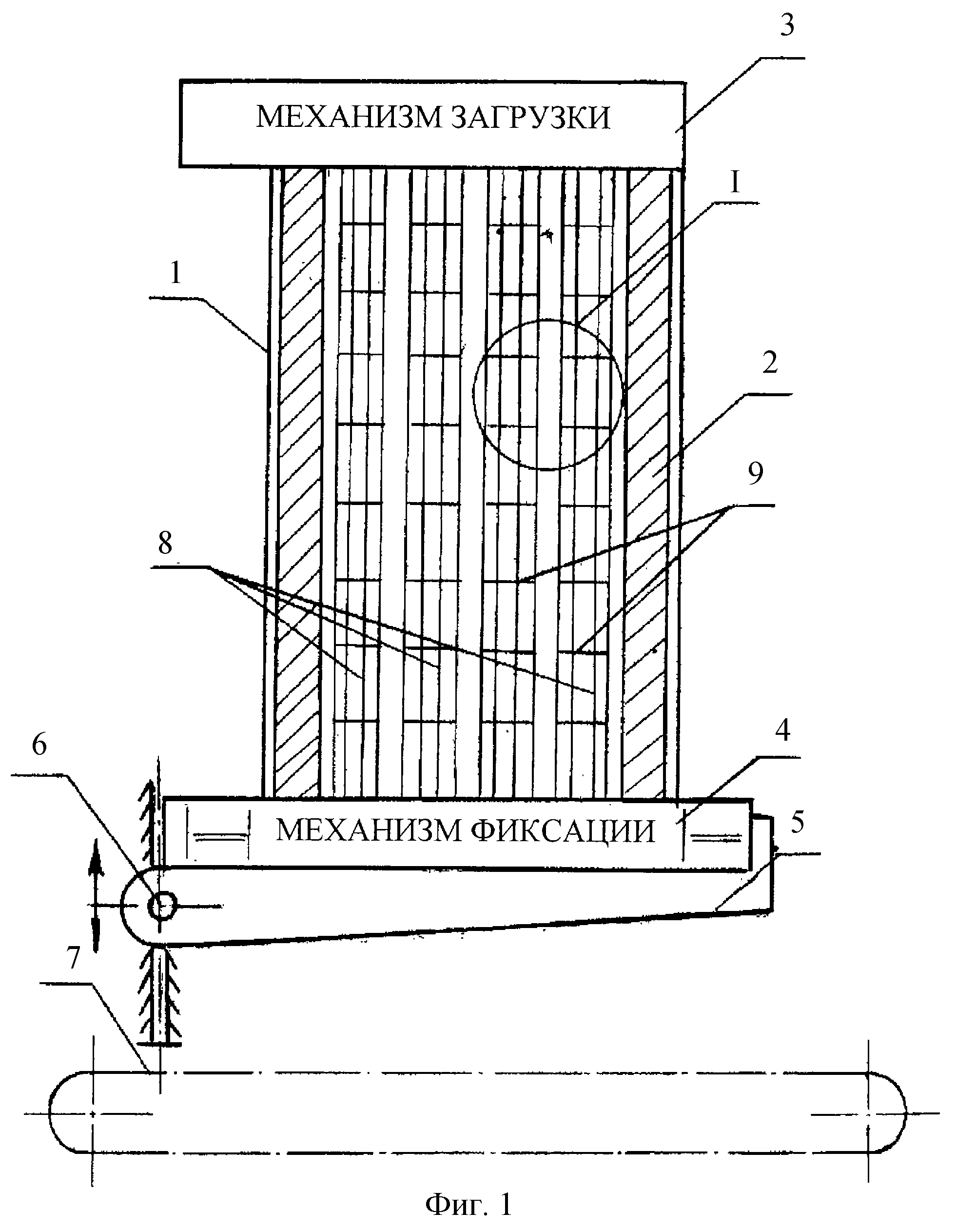

,
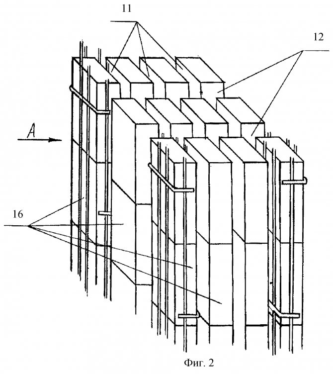

,
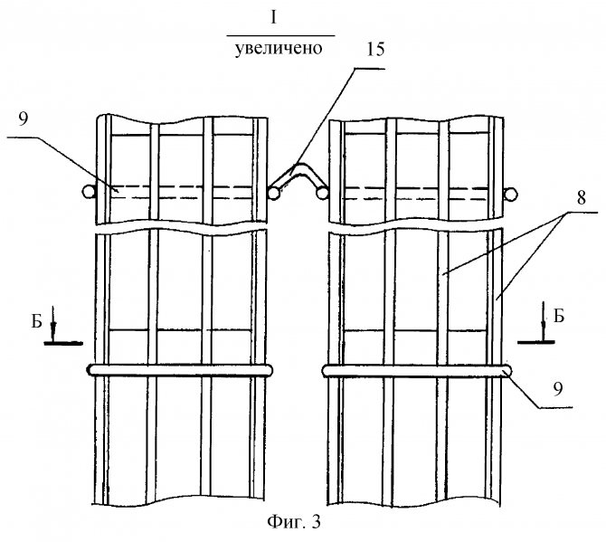

,
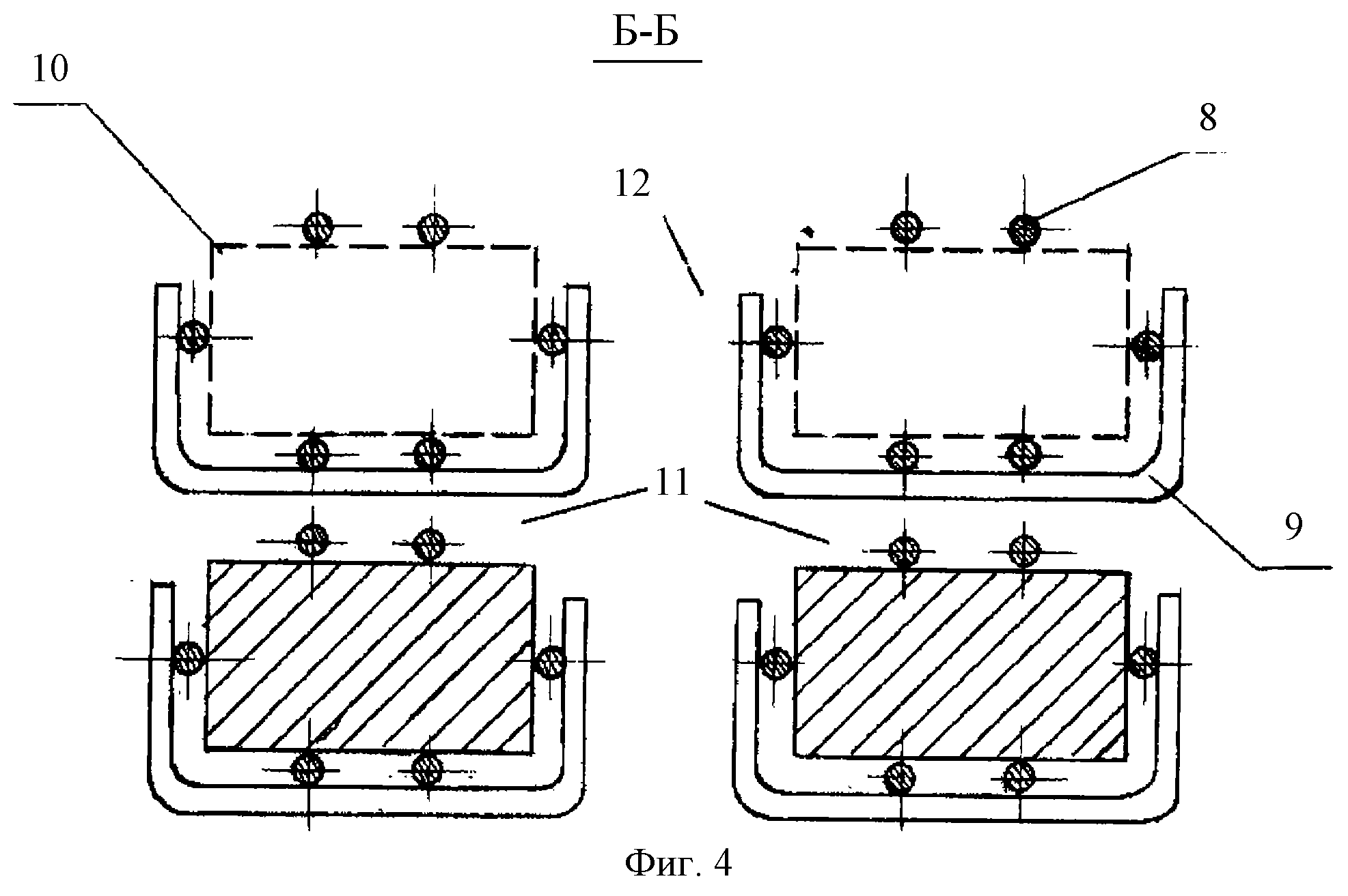

,
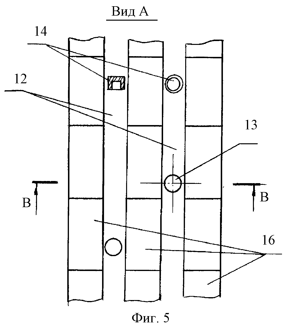

,
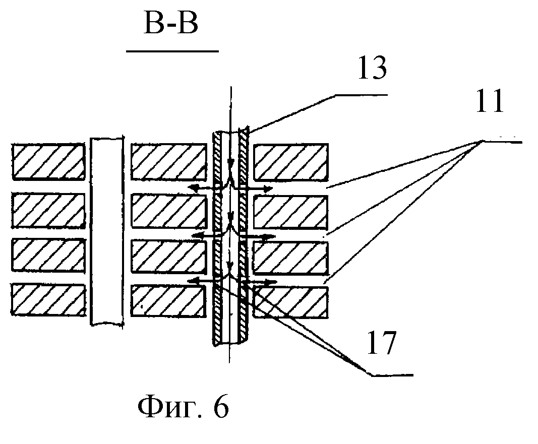

,

,

,

,

We build a furnace for firing ceramics with our own hands
The type of furnace is selected based on the number of products to be fired. If the volume is small, we make an oven 250-300 liters. For larger work, you will need large furnace, the size of a small room.
Instruments
To build a small kiln, you need the following tools:
- Locksmith tools - for working with metal. Welding machine, set of wrenches, files, angle grinder (angle grinder), drill, hammers.
- For working with fireclay bricks and ceramics - bricklayer's hammer, trowel, diamond disc for angle grinders.
- Individual protection means. A respirator, goggles, gloves and thick cotton clothing are a must when working with angle grinders and mineral wool.
Work order
The furnace consists of a body, burner, ceiling, insulated chamber, lid.
Construction sequence:
- Housing. We choose a rectangular metal box if fireclay bricks or a metal barrel are used as lining, if we insulate with mineral refractory wool.
In a cylindrical structure, heat distribution is more even. We weld the legs to the body.
- We put it down to the bottom of the frame lining, put four ceramic insulators from power lines or fireclay bricks per edge - they will serve as overlapping posts.
- We lining the walls and roof. It is better to lay fireclay bricks on mortar. We use high density kaolin or basalt wool. We twist the cylinder from a sheet of cotton wool in several layers to avoid seams - heat loss bridges. Fasten to the walls with an asbestos cord and ceramic buttons. The edges of the top of the insulation are wrapped outward, this will seal and heat insulate the joints of the lid and the body.
- We will overlap on the posts.
With a large weight of products, we use dry masonry from fireclay bricks to overlap, with a small weight - porcelain stoneware tiles of appropriate sizes.
- We install the burner. It can be purchased at gas supply stores. Power is better to pick up not less than 2 kilowatts (depends on the heat loss and the volume of the structure).
- We drill a hole for the burner at the bottom of the body and lining. The flame should not touch the products, this is the main principle of the nozzle placement. Placing the nozzle horizontally makes adjustment and maintenance easier.
- We insulate the cover of the structure. For minimal heat loss, we insulate the entire structure from the outside.
- We leave a hole in the lid for the exit of combustion products and control of the process. We provide a valve for temperature control.
- To take data on the temperature inside the furnace, we install a thermocouple of an electronic thermometer.
The oven is ready. A test run is carried out. If masonry was used with fireclay bricks, then first the furnace is dried in a gentle mode.
How to fire ceramics?
In order to properly fire ceramics, it is important to observe the temperature regime in the oven. Firing takes place in three stages:
- Evaporation of moisture. Products are heated up to 250 ° C and stand at that temperature.
- Glowing up to 900 ° C in a closed oven. Clay sintering takes place.
- Gradual cooling.
The kilns must not only develop the required temperature, but also allow it to be regulated. The design should be as simple as possible, loading and unloading products - easy.
