A classic heating scheme with one heat generator is well known to every home owner. However, by combining a gas and electric boiler in one system, a much greater practical effect can be achieved. They say that such a connection is much more economical than usual. Sounds tempting, doesn't it?
With logical reasoning, doubts arise: how will electricity help save the budget, because its cost is much higher than gas? And why do this at all in terms of the expediency of increasing the power of the units? Isn't it easier to buy just one efficient boiler?
In fact, the project of such a combination is quite justified. We will tell you in detail how to assemble heating with electric and gas appliances. You will learn about the structure of this system and its feasibility. We will help you draw up a diagram and not miss the important nuances of arranging a combined heating line.
Why install two boilers at once?
The role of the leader in the gas + electro link is usually performed by a gas unit. This is logical if only because of the lower cost of the fuel used in the supply. But the word “save” was mentioned above, and it is not clear what the cost reduction is.
The fact is that in many regions the tariff for electricity is based on the day / night system. In some cases, it turns out at least quite a bit, but it is more economical than paying for gas. The difference is doubtful, however, it can serve as an additional reason for the accumulation of arguments for the double link.
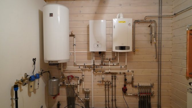
The installation of an electric boiler in conjunction with a gas boiler can play a backup or additional role in the overall organization of heat supply. When choosing the power of the equipment, one should focus precisely on the purpose of its use.
Of course, this is not such a compelling reason to immediately design a heating system with 2 boilers. The main advantages of the circuit are power amplification and uninterrupted operation. When choosing and installing a heat generator, it is necessary to clearly understand that any device and fuel supply will not last forever.
They turn off the power supply, they can cut off the gas main due to a leak, the voltage in the network will drop, or a banal breakdown of the unit itself will occur. In this case, you run the risk of being left without heat and hot water during the cold season.
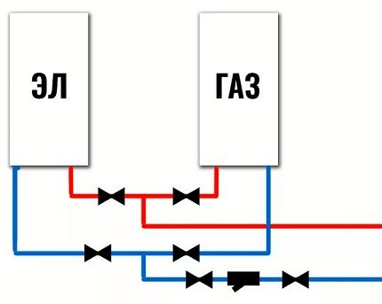

To ensure the uninterrupted operation of heating equipment or to increase the capacity of the system as a whole, it is possible to allow 2 boilers operating on different fuels to operate at once
This is called connecting an additional (for power amplification) or backup power supply, depending on the goals and situations that arise.
Methods for connecting wood and gas boilers into one system
Since a wood-fired boiler operates in an open system, it is not easy to combine it with a gas-fired heater, which has a closed system. With an open-type piping, water is heated to a temperature of one hundred degrees and above at the highest high pressure. To secure overheating of the liquid, an expansion tank is installed.
Part of the hot water is discharged through the open tanks, which helps to reduce the pressure in the system. But the use of such release tanks sometimes becomes the reason for the ingress of oxygen particles into the coolant.
There are two ways to connect two boilers into one system:
- parallel connection of a gas and solid fuel boiler together with safety devices;
- series connection of two boilers of different types using a heat accumulator.
Heat storage application
A heating system with two boilers has the following structure:
- heat accumulator and gas boiler are combined with heating devices in a closed circuit;
- energy flows from the wood-burning heater to the heat accumulator are transferred to a closed system.
With the help of a heat accumulator, it is possible to carry out the operation of the system simultaneously from two boilers or only from a gas and wood heating unit.
Parallel closed circuit
To combine the systems of a wood and gas boiler, the following devices are used:
- safety valve;
- membrane tank;
- pressure gauge;
- air vent valve.
First of all, shut-off valves are mounted on the nozzles of two boilers. A safety valve, a device for venting air, and a pressure gauge are installed near the wood-burning unit.
A switch is placed on the branch from the solid fuel boiler for the operation of the small circle turnover. Fix it at a distance of one meter from the wood-burning heater. A check valve is added to the jumper, blocking the access of water to a part of the circuit of the pumped-out solid fuel unit.
The return flow is connected to the radiators. The return flow of the heating medium is divided by two pipes. One is connected through a three-way valve to the jumper. Before branching these pipes, a tank and a pump are mounted.
In a parallel heating system, a heat accumulator can be used. The installation diagram of the device with such a connection consists in connecting the return and supply lines, supply and return pipes to the heating system to it. For the joint or separate operation of boilers, taps are installed on all system nodes that shut off the flow of the coolant.
Shared connectivity
It is not so easy to design a conventional gas-fired heating system. That is, it is easy to create a working scheme, but it is problematic to get it approved. The situation with electric boilers is less deplorable in terms of costs, time and problems with obtaining documents approving the procedure.
And here is the combination of 2 multi-fuel units. It would seem that you will not get away with problems and you will go to the authorities literally for years, for permits. But this is not the case.
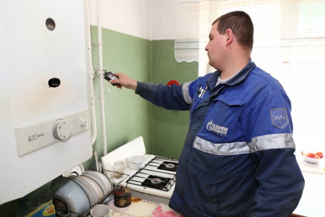

There are no restrictions on the joint use of a gas and an electric boiler in the regulatory documents. However, it is still necessary to agree on such a project in the gas service and obtain permission if you exceed the established limit in the total capacity of the equipment for the use of electricity.
In fact, building codes are quite supportive of such schemes. To be more precise, there are no prohibitions.
Energy and fuel consumption meters are different. The consumption of resources is not exceeded, an explosive situation is not provoked - install the boilers, observing the standard standards, installation instructions for each. There shouldn't be any problems.
We remind you that the installation of gas boilers should be carried out in accordance with SP 402.1325800.2018 (moreover, this document is mandatory, not advisory).
Wiring diagram for two boilers with manual control
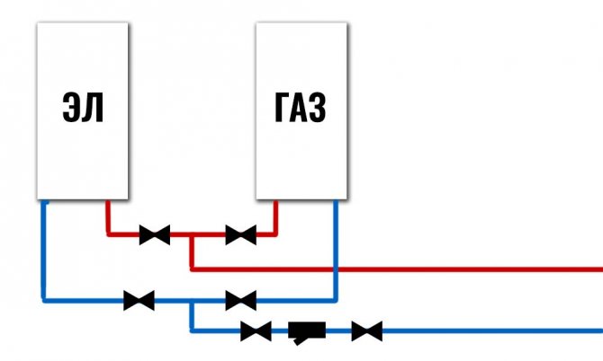

Nothing is required here, except for shut-off valves. Switching between boilers is carried out by manual opening / closing of two taps located on the coolant. And not four, to completely cut off the idle boiler from the system. Both boilers most often have built-in expansion tanks and it is more profitable to use both of them at the same time, because the volume of the heating system very often exceeds the capacity of one expansion tank taken separately.In order to avoid the useless installation of an additional (external) expansion tank, it is not necessary to completely cut off the boilers from the system. It is necessary to shut them off according to the movement of the coolant and leave them simultaneously included in the expansion system.
How to connect 2 boilers in the system?
You can't just take and randomly connect 2 devices, the system will either not work, or it will work incorrectly. It is necessary to use carefully designed, competently designed from an engineering point of view.
There are two main connection schemes, these are:
- Consistentwhen all elements are connected to each other without additional nodes. In this case, one device will heat the coolant, and the second will heat it up;
- Parallel, in which the devices included in the circuit have 2 connection nodes and the boilers work independently of each other.
The sequential system is more suitable for low-power boiler installations and is rarely used.
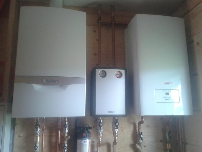

Serial connection is considered impractical, if only because it is impossible to remove one boiler without affecting the second. In fact, the problem is solved by installing bypasses and shut-off valves, but still parallel connection is preferable
Meanwhile, parallel connection in a single system of gas and electric boilers has a lot of advantages. Therefore, it is it that is used most often, despite the fact that this arrangement requires more materials and is considered more expensive.
In such a device, you can turn off one of the devices at any time and even remove it for replacement or repair, the second will continue to work normally.
Closed system with two boilers
Such a scheme provides parallel connection of two boilers... Particular attention is paid to the safety group. Instead of an open expansion tank, a closed diaphragm tank is installed in a special room.
The security group consists of:
- Air bleed valve.
- Safety valve to reduce pressure.
- Pressure gauge.
The strapping is done according to the following scheme:
- Cut-off valves are installed at the outputs of the heat exchangers of both boilers.
- A security group is installed on the supply line, which departs from the solid fuel device. The distance between it and the valve can be small.
- Connect the supply pipes of both boilers. At the same time, before connecting to a line that departs from a solid fuel boiler for a house, a jumper is cut in (to organize a small circle). The tie-in point can be located at a distance of 1-2 m from the boiler. A reverse petal valve is placed at a short distance from the jumper. If the wood-burning boiler stops working, the coolant under the pressure created by the gas unit operating from the cylinder will not be able to move along the supply line towards the solid fuel device.
- The supply line is connected to heating radiators located in different rooms and at different distances from each other.
- The return line is mounted. It should be located between the radiators and boilers. In one place it is divided into two pipes. One of them will be suitable for a gas boiler. On it a return spring valve is placed in front of the unit... The other pipe must fit the solid fuel boiler. The aforementioned jumper is connected to it. A three-way valve is used for connection.
- Before branching the return line, it is worth installing a diaphragm tank and a circulation pump.
Parallel Features
Let's take a closer look at what a standard scheme for parallel connection of gas and electric boilers looks like:
- Each unit is supplied with coolant supply circuits. They join a common line.
- It is imperative in this case that there are safety groups and shut-off valves.
- The return lines are connected to the other line, also equipped with shut-off valves.
- A circulation pump is installed on the return line (or at the supply), in front of the unit for aligning the piping circuits.
- The mains of both heating units are connected to the collectors.
- An expansion tank is installed on one of the distribution manifolds. A make-up circuit is also connected to its pipe, equipped with a check valve and shut-off valves.
- From the distribution manifolds there are main branches to the underfloor heating, radiators, a boiler, circulation pumps and valves for draining the coolant from the system are installed on each.
This is not a schematic diagram, but only its main features. In general terms, it gives an idea of how best to connect an additional electric boiler to the main gas boiler. The assembly option can be complicated and improved, for example, with an automation system and a servo drive.
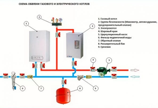

With a parallel connection, you can also install a hydraulic arrow and an automation unit, but before that, carefully consider this solution, their installation is not always advisable
Correct connection of two boilers into one heating system
There are two ways out of the above situation.
Connection of two boilers with manual changeover
You can put the valves in the places indicated in the diagram with green circles:
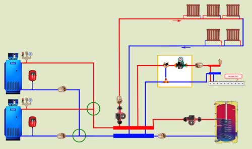

And manually shut off the pipeline with the boiler inoperative. This is not entirely convenient, but it also has a right to exist. Valves for three positions:
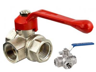

There is a better way, because it allows you to connect two floor-standing boilers so that both of them together or separately can work without unnecessary gestures on our part - just turn on the boiler or both and go about our business.
Connection of two boilers with automatic control
The following diagram for connecting two boilers allows you to automatically control the temperature of the air in the rooms and the temperature of the water in the hot water supply.
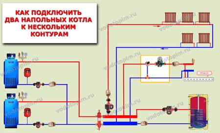

You just need to add a hydraulic arrow. After that, you can connect in one system any number of boilers (also any) with any number of circuits with any consumers.
However, I made a reservation: in addition to the hydraulic arrow, two more pumps were added - one for each boiler.
How does the circuit with a hydraulic gun and two boilers work?
Boiler pumps supply the coolant from the water gun to the boilers, where it heats up and goes back to the water gun. From the hydraulic arrow, the coolant is disassembled by the pumps of the circuits - each takes as much as he needs, without obstacles. If the flow rates through the boilers and through the circuits differ, then part of the coolant will simply fall or rise inside the hydraulic arrow, adding to where there is a lack of it. And the whole system will work stably.
Manual start / automatic control options
The control of the boiler redundancy system or shutdown of the failed ones can be carried out manually or in automatic mode. Leaving the system running with one boiler turned off is impractical, as the water will continue to circulate.
Imagine what will happen when the cooled return flow goes in the opposite direction and starts mixing with the supply, cooling the coolant and forcing the pump to work in vain.
If for some reason you do not want to equip boilers with complex devices, you will start the unit yourself. That is, everything is standard: you need to turn on the device - turn all the necessary valves and turn it on. When disconnecting, proceed in the reverse order.
If you want the backup equipment to be started in automatic mode, the system is equipped with automation, thermostats, indoor and outdoor air temperature sensors, coolant temperature sensors, and servo drives.
In the schematic diagram of the automatic backup start of the heating unit, all shut-off valves must be in the open position. According to the counter scheme, the system is equipped with check valves in order to avoid parasitic circulation of the coolant through the boiler that is not working at a certain time.
However, despite the convenience, the system can cause certain problems, for example, the hydraulic resistance of the check valves, which causes stress on the pumps, contamination and wear of the devices themselves.
To automatically turn on the heating boiler, the system is equipped with a thermostat that sends commands to the control unit, depending on the temperature conditions in the house. The switch-on time for night standby use is set on a timer. The circulation pump is turned off by a magnetic starter.
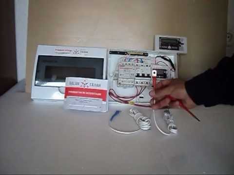

Automation for electric boilers can be built-in, home-made or purchased separately. However, you should not install it with your own hands only on advice from the Internet, without having the proper skills. Invite the wizard for installation and correct system settings
When choosing a control that will be equipped with an electric boiler installed in parallel with a gas boiler, you should opt for automation, if:
- The reserve boiler is turned on at night, when it is inconvenient to start manually.
- In case of long departures from home during the heating season.
- If the gas boiler is unreliable.
In other cases, it is quite possible to use the simplest manual scheme.
Dual fuel heating boilers
In an effort to obtain high performance of the heating system, to avoid interruptions in the voltage in the electrical network and in the operation of the unit, many turn to the installation of dual-fuel boilers. Despite their large size and solid weight, combi boilers function well due to the use of different types of fuel and minimal maintenance costs.
The scheme, in which gas and firewood are used to heat the coolant, is considered the most popular and convenient, since it works with an open heating system. If you want to install a closed system, then it is recommended to put an additional circuit for the heating system in the tank of a universal boiler.
Related article: How to install a wall-hung toilet - we save space wisely
Manufacturers of heating boilers produce several types of dual-fuel combined boilers:
- gas with liquid fuel;
- solid fuel gas;
- solid fuel with electricity.
Solid fuel boiler and electricity
One of the financially justified and functionally convenient combined boilers is considered to be a solid fuel boiler with an electric heater that allows you to control and regulate the temperature in the house. Thanks to the use of heating elements, such boilers have a number of advantages and positive characteristics. Let us consider in more detail the principle of operation of the heating system of a combined boiler.
The combi boiler runs on only one type of solid fuel. The water in the circuit begins to heat up when the loaded raw material burns. As soon as the fuel burns out, the thermostat is triggered and the electric heaters are turned off, the water begins to cool down. As a result of a decrease in temperature, the heating element is automatically turned on to heat the water. The heating and cooling process is cyclical, so a comfortable temperature is constantly maintained in the house.
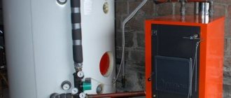
To optimize the operation of the circuits, manufacturers suggest using heat accumulators in heating systems. Outwardly, they are a container with a volume of 1.5 to 2 cubic meters. Principle of operation: the pipes of the circuit pass through the accumulator tank and heat the available water.After the end of the operation of the boiler, hot water slowly gives up heat energy to the heating system. Thanks to the batteries, the temperature regime is maintained stably for a long time.
Summing up, it can be noted that to reduce the cost of heating a private house, to ensure uninterrupted and stable operation of the heating system, installing a dual-fuel boiler is the best and proven option.
Hydro arrow in the system of parallel connection
Hydrostrelka is a device that provides hydraulic decoupling of flows supplied to individual circuits of the heating system. It plays the role of a buffer tank that receives the flow of the heat carrier heated by boilers and distributes it to consumers in a branched system.
Often the volume of the coolant required for them differs, the speed of movement of heated water and its pressure differ. And in the situation under consideration, the movement of heated water from each of the boilers also stimulates its own circulation pump.
When a powerful pump is turned on, an uneven distribution of the coolant along the circuits occurs. So, the task of the hydraulic arrow is to equalize this pressure. Due to the fact that there is practically no hydraulic resistance inside it, it will freely accept and distribute the coolant flows from both boilers.
Let's figure out whether it is really necessary in a parallel system for connecting 2 boilers, especially since if the hydraulic separator is bought and installed with the help of a wizard, and not with our own hands, the total amount will be unpleasantly surprising.
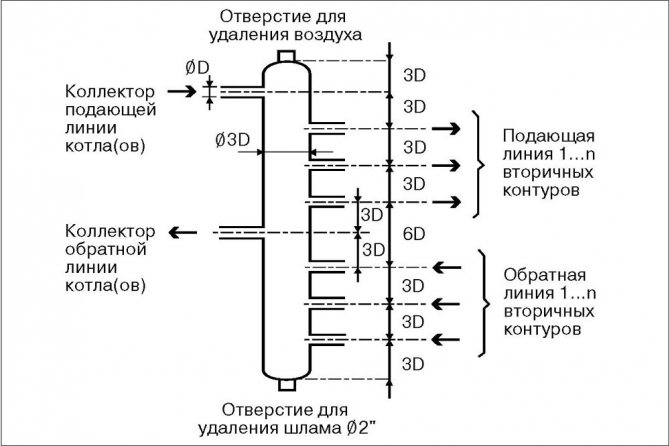

The device is a piece of pipe with nozzles, hollow or with filter nets for removing bubbles and screening out impurities. It can be installed in any position, but more often vertically, equipping the top with an air vent and a shut-off valve for cleaning from below. A hydraulic arrow is installed between the boiler and heating circuits
In the classic wiring diagram, a hydraulic separator is usually not required, since a conflict of 2-3 pumps can be leveled without this device. Accordingly, if you have 2 boilers used exclusively as a backup and there are no more than 3-4 pumps in the system, there is no special need for it.
But if there are more circuits with forced circulation or heating boilers operate simultaneously at power, it is best to install this device. Again, it is not known whether you will use the second boiler permanently or only in standby mode, so it's better to play it safe.
Incorrect connection of two boilers to one heating system
Let's start with how not to do it. It is not necessary to connect boilers like this:
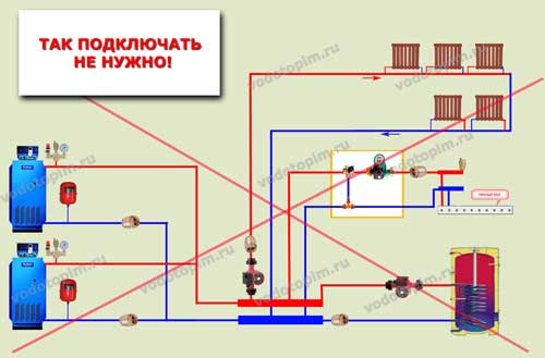

Why? Despite the presence of check valves, running pumps will take heating medium from both boilers, even when one is off.
With two boilers operating, it is also not a fact that the coolant will be supplied to the system evenly: the hydraulic resistances of the circuits are most likely different due to differences in the length of the pipelines.
Conclusions and useful video on the topic
Synchronization of operation and shutdown of boilers in a parallel installation:
Installation of 2 heating boilers, gas and electric, is a wise decision to increase the power of heating equipment, as well as for back-up heating of the building. Parallel installation of units is not as difficult as it might seem at first.
The main thing is to correctly select the arrangement scheme and calculate correctly the total or reserve power of the equipment. If you are not confident in your abilities and cannot handle it on your own, it is best to contact a plumber. They will help you quickly and efficiently install the system for a reliable and comfortable heat supply to your home.
Connection of two boilers into one system
It is possible to combine two heaters using manual and automatic control.
Manual connection
The boilers are turned on and off manually using two taps on the coolant. The piping is carried out using shut-off valves.
Expansion tanks are installed in both boilers, which are used simultaneously. Experts recommend not to completely cut off the boilers from the system, but simply connect them to the expansion tank at the same time, blocking the water flow.
Automatic connection
A non-return valve is installed for automatic regulation of two boilers. It protects the outages of the heating unit from harmful flows. Otherwise, the method of circulation of the coolant in the system is no different from manual control.
Wiring diagram for two boilers with automatic control
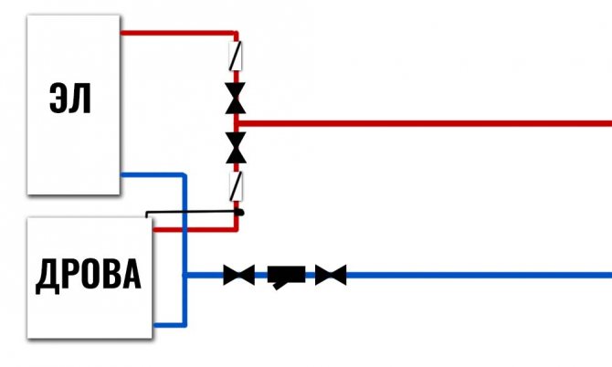

Hydraulically, it is no different from a manual system except for one detail. When connecting two boilers, two check valves appear. The non-return valve is necessary in order to exclude parasitic flows through the idle boiler. There is no need to overlap anything manually in this system. Highways must always be open. And if one of the boilers does not work, then the pump of the second boiler will inevitably drive the coolant through it. From the place where the boilers are connected to the system, the coolant will move towards the heating system and in a small circle through the idle boiler. The resistance in the area with a non-working boiler is much less than the resistance of the heating system. In the area with the boiler turned off, the coolants will go to waste much more than through the heating system, where its deficit will be felt. Check valves solve this problem. The same problem can be solved by means of a hydraulic arrow, but then this will already be a different system and other costs. Check valves can be installed, for example, on the return line.
Important! The valves must work towards each other, then the coolant from the two boilers will move only in one direction, towards the heating system.
For an automatic system for the simultaneous operation of two boilers, an additional part will be needed - this is a thermostat that will turn off the circulation pump if there is a wood boiler or any other boiler with manual loading in the system. It is imperative to turn off the pump at the boiler. Because when the fuel burns out in it, there is no point in wasting the coolant through this boiler, interfering with the operation of the second boiler. Which will pick up the work when the first one stops. With the maximum diameter and the highest brand of thermostat to turn off the pump, you will spend no more than 4000 rubles and get an automatic system.
